



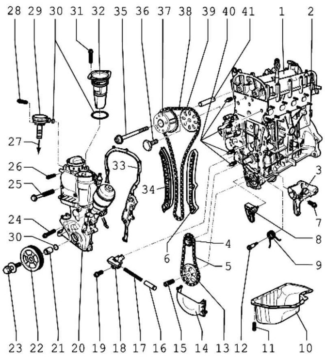
Fig. 2.12. Cylinder block components: 1 – Cylinder head with camshaft housing; 2 – cylinder block; 3 – holder; 4 - star; 5 – drive chain; 6 – damper bar; 7 – bolt 25 Nm; 8 – chain tensioner with bar; 9 – spring; 10 – oil pan; 11 – bolt 15 Nm; 12 – bolt 15 Nm; 13 – asterisk; 14 – lid; 15 – bolt 20 Nm + tighten by 1/4 turn (90°); 16 – piston; 17 – spring; 18 – chain tensioner; 19 – bolt 9 Nm; 20 – timing cover; 21 – support sleeve; 22 – belt pulley; 23 – mounting bolt; 24 – bolt 10 Nm; 25 – bolt 50 Nm; 26 – bolt 10 Nm; 27 – to the intake manifold; 28 – bolt 10 Nm; 29 – vacuum valve; 30 – O-ring with O-ring section; 31 – bolt 10 Nm; 32 – oil separator; 33 – gasket; 34 – tensioner bar; 35 – bolt 40 Nm + tighten by 1/4 turn (90°); 36 – bolt 50 Nm + tighten by 1/4 turn (90°); 37 – phase shifter; 38 – timing chain; 39 – asterisk; 40 – guide bolt; 41 – support sleeve
Note: If, during engine repair, large quantities of metal shavings and dust are found in the engine oil – the source of which is increased wear, for example, due to damage to the connecting rod bearing – then in order to avoid subsequent damage, in addition to cleaning the lubrication channels, it is necessary to replace the oil filter.
Note: All support and working surfaces must be lubricated with engine oil before installation.
Visitor comments