
Attention: The crankshaft must not be removed. Even unscrewing the bolts of the main bearing caps leads to deformation of the bearing racks of the cylinder block. Due to such deformations, the clearance in the bearings decreases. Even if the bearing shells are not replaced, they can be damaged due to the changed clearance in the bearings.
Attention: If the bearing cap bolts have been removed, the entire cylinder block must be replaced together with the crankshaft.
Attention: It is not possible to measure the clearance in the main bearings in the conditions of a service station
Removing
Remove the front right fender liner.
Remove poly V-belt.
Rotate the crankshaft in the direction of engine rotation to the TDC of the first cylinder.
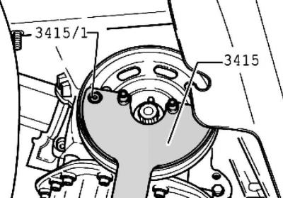
Pic. 2.16. Lock key
Loosen the belt pulley bolt. Hold the belt pulley with the lock key (pic. 2.16).
Unscrew the central bolt and remove the crankshaft pulley.
Unscrew the inside of the puller three turns (about 5 mm) from the outside and secure with a knurled screw.
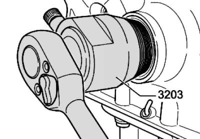
Pic. 2.19. Puller installation
Lubricate the threaded head of the puller with engine oil, install and, pressing hard, screw it as deep as possible into the oil seal (pic. 2.19).
Loosen the knurled bolt and turn the inside of the puller against the crankshaft until the oil seal is pulled out.
Remove the support sleeve from the crankshaft journal and clean the mating surfaces of the crankshaft sprocket and support sleeve.
Installation
Slide the bearing bush onto the crankshaft journal.
Note: Check the mating surfaces of the belt pulley, mounting bolt, bearing bush and crankshaft sprocket for oil and grease.
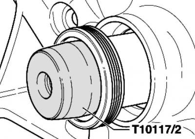
Pic. 2.20. Mandrel installation
Put the mandrel on the bushing and put the oil seal on the bushing (pic. 2.20).
Remove the mandrel from the bushing.
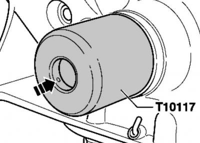
Pic. 2.21. Pressing in the stuffing box
Press in the oil seal with a mounting tool with even blows until it stops (pic. 2.21).
Further installation is carried out in the reverse order.
Visitor comments