
English Русский
Български
Беларускі
Український
Српски
Hrvatski
Română
Polski
Slovenský
Magyar
  |  Articles  |  Sitemap  |  Contacts  |    |
Car maintenance Ford Car maintenance Hyundai Car maintenance Chevrolet Car maintenance BMW Car maintenance Audi Car maintenance Opel Car maintenance AvtoVAZ
VWmanual.ru


Main   Passat   Golf   Polo   Touareg   Tiguan   Sharan   Transporter   Others  
Passat B2 (1981-1988) Passat B3 (1988-1993) Passat B4 (1988-1996) Passat B5 (1996-2005) Passat B6 (2005-2010)

Removal and installation the camshaft housing (VW Passat B6)

  • Main
  • Passat
  • Passat B6
  • Petrol engine 1.6L
  • Engine repair
  • Removal and installation the camshaft housing
            0


Contents: Removal ↓ Installation ↓
Note: This engine has camshafts located in the camshaft housing. The timing cover must be removed before removing the camshaft housing.


Note: The camshaft housing seating surface must not be machined.


Removal


First, you need to check whether the car has a radio with coding. If so, you should find out the security code.

Disconnect the ground wire from the battery with the ignition off.

Remove the timing cover.

Turn the crankshaft to TDC of the first cylinder, then turn the crankshaft back against the direction of engine rotation by approximately 45° and remove the camshaft sprockets with the timing chain.

Remove the EGR valve and unscrew the camshaft covers.

Disconnect the low pressure fuel pressure sensor plug.

Unscrew the ground cable from the camshaft housing.

Remove the ignition coils. Use a puller to do this.

Remove the wiring box with the wiring harness from the camshaft housing.
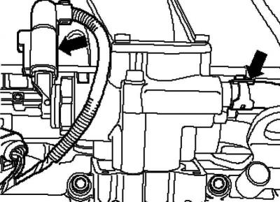
Fig. 2.39. Plug and fuel supply line

Fig. 2.39. Plug and fuel supply line


Disconnect the plug and fuel supply line from the high pressure pump (Fig. 2.39).

Remove the guide and remove the clamp from the high pressure line.


Note: When loosening the union nuts, hold the threaded connections on the high pressure pump and the lower part of the intake manifold with a wrench.


Unscrew union nuts 3 and 1 of the high pressure line.

Disconnect the plug from the Hall sensor.

Remove the dipstick.

Remove the lower portion of the intake manifold.

Unscrew the left hanging eye.

Loosen and remove the camshaft housing mounting bolts from the edges to the center, alternating crosswise.

Carefully lift the camshaft housing.

Installation


Remove any remaining sealant from the cylinder head and camshaft housing with a standard sealant remover.

Note: Pistons should not be at TDC.


Prevent dirt and sealant residue from getting into the cylinder head.

Clean the mounting surfaces thoroughly. They must be free of oil and grease.

Rotate the intake and exhaust camshafts until the camshaft locking pin fits into the camshaft holes as far as it will go.

To secure the retainer, screw in the M6 bolt by hand; without delay.
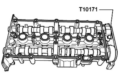
Fig. 2.40. Applying sealant

Fig. 2.40. Applying sealant


Apply sealant to the clean camshaft housing mounting surface in a thin, even bead, see shaded area in Figure 2.40.


Note: The sealant bead should not be too thick, otherwise excess sealant may enter the oil passages, causing engine damage.
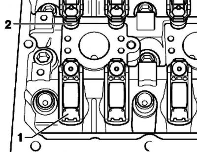

Fig. 2.41. Installing valve stems into the corresponding support elements

Fig. 2.41. Installing valve stems into the corresponding support elements


Make sure that all roller levers are correctly applied to the ends of the valve stems 1 and clipped into the corresponding support element 2 (Fig. 2.41).

Before installing the camshaft housing, screw two spacer bolts (M6x80) into the cylinder head.

Carefully place the camshaft housing vertically on top of the spacer bolts and cylinder head dowel pins.

Note: Avoid contact of oil with adjacent surfaces.


Tighten the new camshaft housing mounting bolts evenly in a crisscross pattern, alternating from the center outward.

Make sure that the camshaft housing is not warped. Tightening torque 10 Nm + tighten by 1/4 turn (90°)

Note: After installing the camshaft housing, allow the sealant to dry for approximately 30 minutes.


Adjust the valve timing.

Further installation is carried out in reverse order.

Install the timing cover.

Connect the fuel lines.

Install the EGR valve

[View the original on this portal www.VWMANUAL.ru]

This article is available at russian, bulgarian, belarusian, ukrainian, serbian, croatian, romanian, polish, slovak, hungarian
The text has been checked: Orlov Dmitry

Share information:

Previous articles
Adjusting the valve timing
Checking the valve timing
Cylinder head
Disassembly and assembly of pistons and connecting rods
Method of tightening the belt drive sprocket mounting bolt
Replacing the crankshaft oil seal on the belt pulley side
Next articles
Removal and installation the cylinder head
Compression check
Valve mechanism repair
Checking the valve guides
Replacing valve stem seals


Similar articles from other manuals for VW cars:
Timing Belt (Camshaft Drive Belt) Golf 1 (1974-1984, petrol)
Removal and installation the camshaft housing Polo 3 (1995-2003)
Replacing camshaft seals Touareg 1 (2002-2006)
Camshaft drive chain Tiguan 1 (2007-2015)
Replacing the camshaft seal Sharan 1 (1995-2000)
Removal and installation the camshaft Transporter T4 (1990-2003)
Checking the camshaft timing belt (SDI and TDI diesel engines) Caddy 3 (2003-2010)
Link to this page in different formats


Visitor comments


No comments yet


How much will 27 + 49 =


Passat B6 
  • General information
  • User manual
  • Maintenance
  • Petrol engine 1.6L
  • Engine repair
  • Cooling and lubrication system
  • Fuel injection system
  • Petrol engine 2.0L
  • Engine repair
  • Lubrication system
  • Cooling system
  • Fuel and exhaust systems
  • Diesel engine 2.0L
  • Engine repair
  • Cooling and lubrication system
  • Fuel and exhaust systems
  • Transmission
  • Clutch
  • Mechanical gearbox
  • Automatic gearbox
  • Drive shafts
  • Chassis
  • Wheels and tires
  • Car suspension
  • Steering
  • Brake system
  • Body
  • Exterior (external elements)
  • Electrical equipment
  • Power devices
  • Lighting and appliances
  • Electrical circuits
Passat B5 
  • General information
  • User manual
  • Weekly checks
  • Maintenance
  • Power unit
  • Engine repair
  • Cooling system
  • Fuel system (petrol)
  • Fuel system (diesel)
  • Engine management
  • Exhaust system
  • Transmission
  • Clutch
  • Car gearbox
  • Drive shafts
  • Chassis
  • Car suspension
  • Wheels and tires
  • Steering
  • Brake system
  • Body
  • Exterior (external elements)
  • Interior (internal elements)
  • Doors and covers
  • Ventilation and heating
  • Electrical equipment
  • Power devices
  • Lighting and appliances
  • Electrical circuits
Passat B4 
  • General information
  • User manual
  • Maintenance
  • Technical data
  • 8-valve engine
  • Engine repair
  • Cooling and lubrication system
  • Supply system
  • Ignition system
  • Fuel injection «Mono-Jetronic»
  • Control system «Mono-Motronic»
  • Control system «Digifant»
  • Control system «Simos»
  • 16-valve engine
  • Engine repair
  • Cooling and lubrication system
  • Fuel injection «K-Jetronic»
  • Control system «KE-Motronic»
  • Control system «Digifant»
  • Diesel engine
  • Engine repair
  • Cooling and lubrication system
  • Power and control system
  • Turbocharging system
  • Digital control system
  • Transmission
  • Clutch
  • Manual gearbox
  • Hydromechanical gearbox
  • Front wheel drive
  • Chassis
  • Car suspension
  • Steering
  • Brake system
  • Body
  • Body elements
  • Electrical equipment
  • Power devices
  • Lighting and appliances
  • Electrical circuits
Passat B3 
  • General information
  • User manual
  • Driving Tips
  • Maintenance instructions
  • Technical data
  • Power unit
  • Engine repair
  • Ignition system
  • Lubrication system
  • Cooling system
  • Supply system
  • Petrol injection system
  • Diesel engine
  • Exhaust system
  • Transmission
  • Clutch
  • Car gearbox
  • Chassis
  • Suspension
  • Steering
  • Brake system
  • Wheels and tires
  • Body
  • Exterior
  • Interior
  • Heating system
  • Electrical equipment
  • Power devices
  • Lighting system
  • Equipment and devices
  • Wiper system
  • Electrical circuits
Passat B2 
  • General information
  • Introduction to instructions
  • User manual
  • Power unit
  • Engines 4-cylinder FZ
  • Engines 4-cylinder
  • Engines 5-cylinder
  • Transmission
  • Clutch
  • Four-speed gearbox
  • Five-speed gearbox
  • Hydromechanical gearbox
  • Front wheel drive
  • Chassis
  • Front suspension
  • Rear suspension
  • Steering
  • Brake system
  • Body
  • Body elements
  • Electrical equipment
  • Equipment and devices
  • Electrical circuits
VWmanual.ru © 2016-2026 | Mobile version | News and articles | Sitemap: EN BG BY UA RS HR RO PL SK HU | Write message | Site search
Passat B2 • Passat B3 • Passat B4 • Passat B5 • Passat B6 • Golf 1, diesel • Golf 1, petrol • Golf 2, petrol • Golf 2 • Golf 3 • Golf 4 • Golf 5 • Polo 3 • Polo 4 • Touareg 1 • Tiguan 1 • Sharan 1 • Transporter T3 • Transporter T4 • LT 28 • LT 2D • Beetle • Caddy 3 •
Our website uses cookies to ensure functionality and convenience.