



Remove the EGR valve.
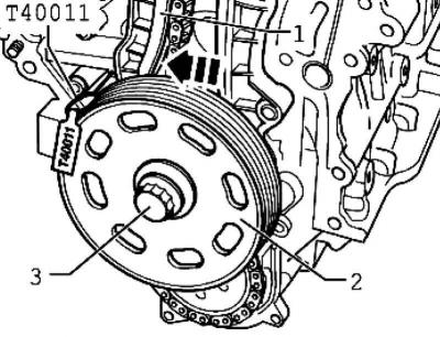
Fig. 2.36. Installing the bolt into the crankshaft belt pulley
To rotate the crankshaft, insert the support sleeve, crankshaft belt pulley 2 and crankshaft bolt 3, then screw in the bolt (use counter support 3415) (Fig. 2.36).
Remove the spark plug from the first cylinder. Use a puller and a spark plug wrench to do this.
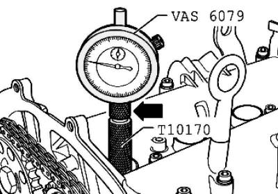
Fig. 2.33. Installing the adapter and indicator
Screw the dial indicator adapter into the spark plug socket until it stops (Fig. 2.33).
Insert the dial indicator with the extension until it stops and press it with the nut.
Rotate the crankshaft in the direction of engine rotation to TDC of the first cylinder. Remember the position of the small arrow of the dial indicator.
Then turn the crankshaft back 45° against the direction of engine rotation.
Press the tensioner bar 1 in the direction of the arrow and secure the piston with the locking pin (Fig. 2.36).
Mark the direction of the timing chain with a felt-tip pen 3.
Note: The central bolt of phase shifter 2 has a left-hand thread.
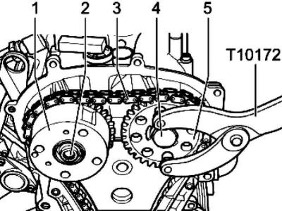
Fig. 2.37. Removing the phase shifter
Unscrew bolts 2 and 4 and remove phase shifter 1 from timing chain 3 (Fig. 2.37). Use a counter support to hold it.
Reinstall phase shifter 1.
Replace bolts 2 and 4 and tighten bolt 2 to 40 Nm and bolt 4 to 50 Nm.
Rotate the intake and exhaust camshafts until the camshaft locking pin fits into the camshaft holes as far as it will go.
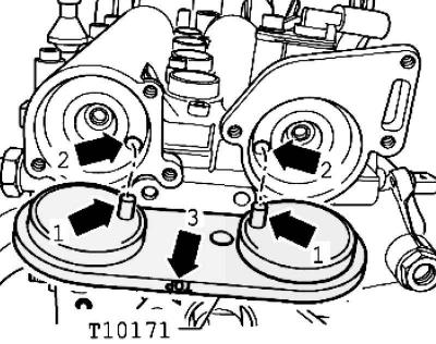
Fig. 2.35. Camshaft locking tool
The locking pins 1 must enter the holes 2. The "TOP" mark must be visible from above (Fig. 2.35).
Note: When cranking, the camshafts must not be moved axially.
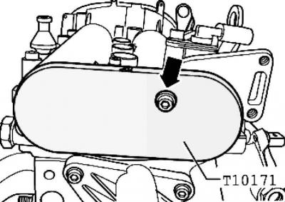
Fig. 2.38. Fastening the retainer
To secure the retainer, screw in the M6 bolt by hand; without tightening it (Fig. 2.38).
Unscrew the camshaft sprocket bolts. Be sure to use a counter support for this.
Note: The camshaft locking tool must not be used as a counter support.
Remove one camshaft sprocket.
Place the timing chain, observing the direction of travel, on the camshaft sprockets and reinstall the removed sprocket.
Tighten the camshaft bolts until the sprockets still turn on the camshafts.
Tighten the timing chain by pulling out the locking pin.
Turn the crankshaft in the direction of engine rotation to the TDC of the first cylinder. The permissible deviation from the TDC of the first cylinder is ±0.01 mm.
Note: If the crankshaft has been turned past TDC by more than 0.01 mm, it should be turned again against the direction of engine rotation by approximately 45°. Finally, bring the crankshaft in the direction of engine rotation to TDC of the first cylinder.
Hold camshaft sprockets 1 and 5 in this position using a counter support and tighten bolts 2 (left hand thread) with a tightening torque of 40 Nm and 4 at 50 Nm (Fig. 2.37).
Note: When tightening the camshaft bolts, the crankshaft must not turn and the timing chain 3 must remain taut on both sides.
Remove the camshaft locking tool.
Turn the crankshaft in the direction of engine rotation by two revolutions to the TDC of the first cylinder. The permissible deviation from the TDC of the first cylinder is ±0.01 mm.
Insert the camshaft locking tool into the holes in the camshafts until it stops.
If the camshaft lock does not fit
Repeat the adjustment.
If the camshaft lock is inserted
Remove the camshaft lock, hold the camshaft sprockets with a counter support and screw in the bolts 2 (left hand thread) and 4 with a regular key for 1/4 turn (90°). (Fig. 2.37).
Note: The central bolt of phase shifter 2 has a left-hand thread.
Note: The sprockets should not rotate on the camshafts when tightening the bolts.
Turn the crankshaft again in the direction of engine rotation by two revolutions to the TDC of the first cylinder. The permissible deviation from the TDC of the first cylinder is ±0.01 mm.
Insert the camshaft locking tool into the holes in the camshafts until it stops.
If the camshaft lock does not fit, repeat the adjustment.
Further installation is carried out in reverse order.
Install the timing cover.
Install the poly V-belt.
Replace the camshaft plug seals and lubricate them with oil before installation.
Install the EGR valve.
Visitor comments