
English Русский
Български
Беларускі
Український
Српски
Hrvatski
Română
Polski
Slovenský
Magyar
  |  Articles  |  Sitemap  |  Contacts  |    |
Car maintenance Ford Car maintenance Hyundai Car maintenance Chevrolet Car maintenance BMW Car maintenance Audi Car maintenance Opel Car maintenance AvtoVAZ
VWmanual.ru


Main   Passat   Golf   Polo   Touareg   Tiguan   Sharan   Transporter   Others  
Touareg 1 (2002-2006)

Adjusting the valve timing (VW Touareg 1)

  • Main
  • Touareg
  • Touareg 1
  • Power unit
  • Petrol engine 3.2L
  • Adjusting the valve timing
            0


NOTE: Install the timing chains. These installation operations can only be performed with the engine removed.


Work execution procedure


ATTENTION: When carrying out any installation work, particularly in the engine compartment due to the tight layout, the following must be taken into account: all types of lines (for example fuel, hydraulic, activated carbon canister, cooling systems, air conditioning circuits, brake lines, vacuum hoses), and electrical wires must be routed as originally installed. Provide clearance for all moving and hot components.


NOTE: The camshaft timing chains can only be removed with the engine removed. The following operations begin with the engine disassembled. This allows you to begin the adjustment from the appropriate location depending on how much the engine has been disassembled.


Install the roller chain and intermediate shaft chain tensioner with tension bar.

Adjust the position of the crankshaft in relation to the intermediate shaft. To do this, the ground tooth of the drive sprocket B must coincide with the joint of the bearing "TDC cylinder 1" (Fig. 2.70).
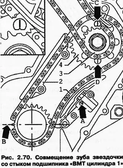
Adjust the position of the crankshaft in relation to the intermediate shaft. To do this, the ground…


Fit both flangeless bolts for securing guide rail 2 and tighten them to a torque of 10 Nm.


NOTE: If the roller chain has been used previously, the specified direction of rotation must be taken into account.


Install guide bar 2 with roller chain 1 and both chain sprockets 3 and 4. The mark on sprocket 4 of the roller chain must be aligned with notch C or D on the adjusting washer of the intermediate shaft (Fig. 2.70).

When installing, it is necessary to ensure that the roller moves inside the guide bar from the crankshaft to the intermediate shaft without any sagging.

Manually screw chain sprockets 3 and 4 to the intermediate shaft.

NOTE: Please note that all sprocket mounting bolts must be replaced.


Install the chain tensioner on the opposite side.

Release the chain tensioner locking gear A using a small screwdriver and press the tension bar against the chain tensioner.

In this position, install the chain tensioner and tighten it to a torque of 8 Nm.

Secure the vibration damper using the T10069 locking key.

Tighten the new sprocket 3 and 4 mounting bolt for the intermediate shaft chain drive to a tightening torque of 60 Nm + 1/4 turn (90°).

Remove counter support T10069.

Check again the position of crankshaft B in relation to intermediate shaft C or D (Fig. 2.70).

Bring the engine back to TDC position for cylinder 1.

Install the camshaft drive roller chain.

Bring the installed camshafts in the main cylinder head to the TDC position of cyl. 1.

NOTE: If necessary, turn the camshafts with a 32 mm spanner to the correct position.


NOTE: The T10068A camshaft ruler must not be inserted into the grooves.

This article is available at russian, bulgarian, belarusian, ukrainian, serbian, croatian, romanian, polish, slovak, hungarian
The text has been checked: Tarasov Ivan

Share information:

Previous articles
Checking the valve timing
Removal and installation the cylinder head
Removal and installation the cylinder head cover
Removal and installation the side cover
Removal and installation the crankshaft
Replacing the crankshaft sealing flange on the vibration damper side
Next articles
Removal camshafts
Installing camshafts
Checking the axial displacement of the camshafts
Marking of camshafts
Replacing valve stem seals
Checking the valve guides


Similar articles from other manuals for VW cars:
Removal and installation the throttle valve control unit and the… Tiguan 1 (2007-2015)
Removal and installation valve 1 of the valve timing regulator Passat B6 (2005-2010)
Throttle Damper and Timing Valve — checking and adjusting LT 28 (1975-1991)
Checking and adjusting the valve timing Transporter T3 (1979-1992)
Timing belt and timing gears Golf 2 (1984-1993, petrol)
Checking and adjusting the ignition timing angle Polo 3 (1995-2003)
Link to this page in different formats


Visitor comments


No comments yet


How much will 50 + 13 =


Touareg 1 
  • General information
  • Vehicle device
  • Controls and instruments
  • Seats and safety
  • Maintenance and management
  • Power unit
  • Engine checks
  • Petrol engine 3.2L
  • Petrol engine 4.2L
  • Diesel engine 5.0L
  • Cooling system
  • Lubrication system
  • Injection system
  • Exhaust system
  • Fuel supply system
  • Transmission
  • Automatic gearbox 09D
  • Mechanical gearbox 08D
  • Cardan shaft
  • Chassis
  • Wheels and tires
  • Front suspension
  • Rear suspension
  • Steering gear
  • Brake system
  • Body
  • Outdoor elements
  • Electrical equipment
  • Battery
  • Generator and starter
  • Instruments and wipers
VWmanual.ru © 2016-2026 | Mobile version | News and articles | Sitemap: EN BG BY UA RS HR RO PL SK HU | Write message | Site search
Passat B2 • Passat B3 • Passat B4 • Passat B5 • Passat B6 • Golf 1, diesel • Golf 1, petrol • Golf 2, petrol • Golf 2 • Golf 3 • Golf 4 • Golf 5 • Polo 3 • Polo 4 • Touareg 1 • Tiguan 1 • Sharan 1 • Transporter T3 • Transporter T4 • LT 28 • LT 2D • Beetle • Caddy 3 •
Our website uses cookies to ensure functionality and convenience.