
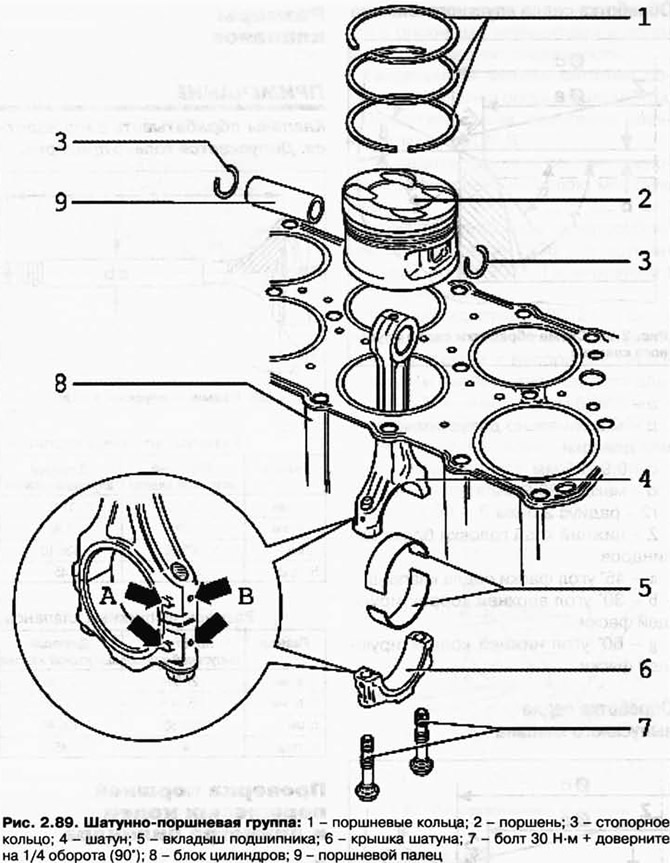
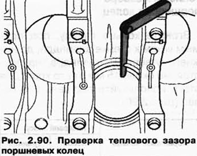
Checking the thermal clearance of the piston rings
Drive the ring from above, at a right angle to the cylinder wall, to the bottom hole of the cylinder, at a distance of about 15 mm from its edge. To do this, use a piston without rings (pic. 2.90).
| Thermal gap | ||
| Piston ring | new | wear limit |
| Rectangular ring, mm | 0,20-0,40 | 1,0 |
| Scraper conical compression ring, mm | 0,20-0,40 | 1,0 |
| Oil scraper ring, mm | 0,25-0,50 | 1,0 |
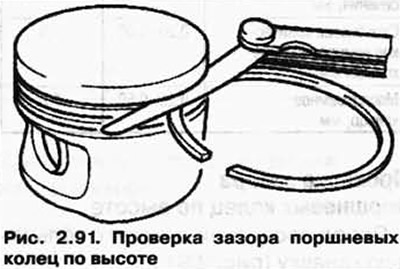
Checking the clearance of piston rings in height
Before checking, clean the annular groove (pic. 2.91.).
| Thermal gap | ||
| Piston ring | new | wear limit |
| Rectangular ring, mm | 0,04-0,09 | 0,15 |
| Scraper conical compression ring, mm | 0,03-0,06 | 0,15 |
| Oil scraper ring, mm | 0,02-0,06 | 0,15 |
Checking the cylinder diameter
Measure about 6 mm from the bottom edge, at right angles to the axis of the piston pin (pic. 2.92).
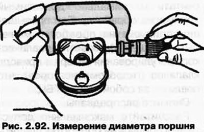
Maximum permissible deviation from the nominal size 0.04 mm
Take measurements crosswise in three places in the transverse direction A and longitudinal direction B (pic. 2.93).
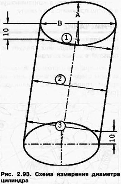
The maximum allowable deviation from the nominal size is 0.08 mm.
NOTE: It is forbidden to measure cylinder diameters when the cylinder block is attached to the engine and gearbox retainer VAS 6095, otherwise incorrect results may be obtained.
Piston and cylinder dimensions
| Grinding size | Piston | Cylinder |
| Nominal size, mm | 83,965 | 84,010 |
Installation of pistons using a funnel T10147
NOTE: When using the new T10147 funnel to install the piston, first pass the piston with oiled piston rings through it twice and remove any chips if necessary (pic. 2.94).
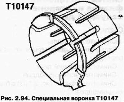
Only then can pistons with rings be installed.
Manually push the plunger into the oiled T10147 funnel. The flat side of the piston crown must point towards the funnel trunnion (pic. 2.95).
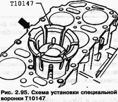
holding the funnel (with a piston) behind the top edge, push the plunger inward by pressing down on it with the thumbs of both hands.
Push the plunger in until it protrudes from the bottom edge of the funnel by about 15 mm.
Place the piston in the appropriate cylinder. Funnel trunnion (pic. 2.95) must face the middle of the cylinder block.
Place a funnel on the cylinder block and push the piston in.
Visitor comments