
NOTE: When repairing engines with leaking valves, treat or replace valve seats and valves insufficiently. Especially in engines with a long service life, the valve guides must be checked for wear.
Valve seats should only be refinished to the extent necessary to achieve a flawless seating surface. Before machining, the maximum allowable machining allowance should be calculated. If the machining allowance is exceeded, the function of the hydraulic clearance control in the valve drive may be impaired (hydraulic compensators), which will entail the replacement of the cylinder head.
Remove the distributors.
Calculate the maximum allowable machining allowance as follows:
- insert the valve into the guide and press it firmly against the seat;
NOTE: If the valve is being replaced during repair, use the new valve for measurements.
- measure distance A between the end of the valve stem and the top edge of the cylinder head (pic. 2.85);
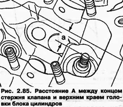
- Calculate the maximum allowable machining allowance based on the measured distance A and the minimum allowable dimension.
Minimum dimensions
| short inlet valve, mm | 31,8 |
| long inlet valve, mm | 10,2 |
| short exhaust valve, mm | 31,8 |
| long exhaust valve, mm | 10,2 |
Measured distance A minus the minimum dimension = max. allowable revision size.
Example:
- Measured distance 10.6 mm
- Minimum size 10.2 mm
- The maximum allowable machining allowance is 10.6-10.2 = 0.4 mm
NOTE: In the following diagrams, the maximum allowable machining allowance for valve seats is shown as Dimension B.
Inlet valve seat processing
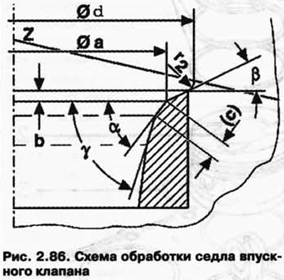
a - 30.6 mm
b - the maximum allowable finishing size
c - 0.9-1.5 mm
d - max. 35.0 mm
r2 - radius 2.0 mm
Z - lower edge of the cylinder head
a - 45°valve seat bevel angle
b - 30°angle of upper corrective chamfer
g - 60°angle of bottom corrective chamfer
Exhaust valve seat processing
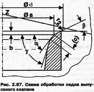
a - 26, mm
b - the maximum allowable finishing size
c - 1.2-1.7 mm d - max. 29.0 mm
r2 - radius 2.0 mm
Z - lower edge of the cylinder head
a - 45°valve seat bevel angle
b - 30°angle of upper corrective chamfer
g - 60°angle of bottom corrective chamfer
Visitor comments