
ATTENTION: For any assembly work, in particular in the engine compartment due to the dense layout, the following must be taken into account:
- highways of all kinds (e.g. fuel, hydraulic, activated charcoal absorber, cooling systems, air conditioning circuits, brake lines, vacuum hoses), as well as electrical wires must be laid as they were originally laid.
- provide free space for all moving and hot components.
- after installation, it is necessary to reinstall all cable fasteners that are removed or cut off during dismantling.
Removing
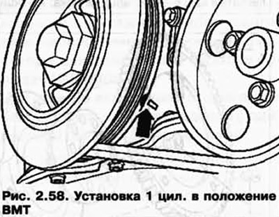
Drive the crankshaft with the vibration damper fixing bolt in the direction of engine rotation to the TDC cyl. 1 (pic. 2.58).
Remove poly V-belt.
Remove the cylinder head cover and intake manifold.
Unscrew the connecting cable 1 on the support bracket for the intake manifold and unplug knock sensor 1 G61 2 from its holder (pic. 2.59).
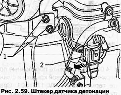
Then unclip the wiring harness from the mount on the MCC.
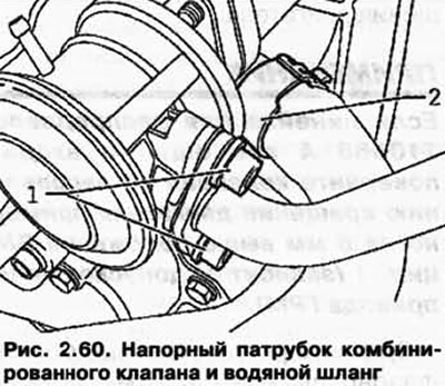
Unscrew the pressure connection from the combination valve 1, then disconnect the water hose 2 under the combination valve from the cylinder head (pic. 2.60).
Unbolt the exhaust manifold from the cylinder head.
Disconnect the connectors from valve 1 for variable valve timing N205 and valve 1 for variable valve timing for exhaust valves N318.
NOTE: Before disconnecting, mark which plugs belong to the part.
Remove the wiring harness clamps from the bracket.
Remove the thermostat housing and cooling system elements mounted on the engine.
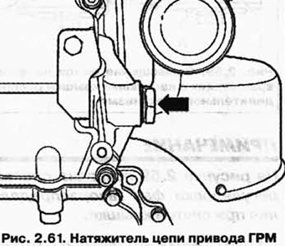
Unscrew the timing chain tensioner (pic. 2.61).
Remove the side cover.
NOTE: The side cover has «hidden bolt». Access to it is provided only after removing the thermostat housing.
After unscrewing all the fixing bolts, carefully pry the side cover down.
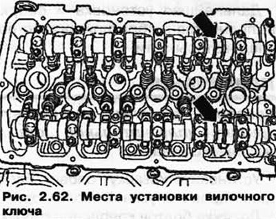
Unscrew the fixing bolts of the phase shifters.
NOTE: When loosening and tightening the phase shifters, hold the camshafts only with a 32 spanner (pic. 2.62). The T10068 A camshaft ruler must not be inserted into the grooves.
Remove the camshaft shifter clutch with the timing roller chain from the intake shaft.
Then remove the exhaust camshaft shifter.
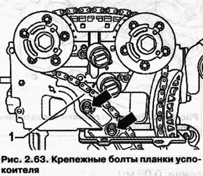
Unscrew the fixing bolts and remove the damper bar 1 (pic. 2.63).
Set the timing chain aside by laying it sideways.
Loosen the cylinder head cover bolts in the specified sequence from the edges to the middle and unscrew them (pic. 2.64).
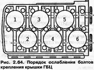
NOTE: For Polydrive head screws, use 3452 wrench.
Suspend the device for hanging 3033, as shown in Figure 2.65, and carefully lift the cylinder head with a crane VAS 6100 or VAG 1202 A.
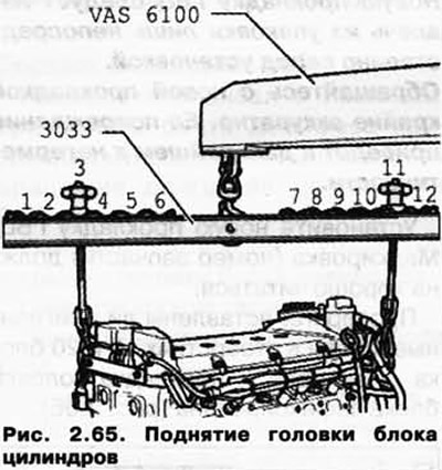
Vibration damper side: position 3.
Flywheel side: position 11.
NOTE: Positions marked 1 to 12 on Hanger 3033 point towards flywheel (pic. 2.65).
NOTE: The lead screws are adjustable in length as needed.
Carefully remove the cylinder head.
Put a clean rag into the cylinders so that dirt and emery residue do not get between the cylinder mirrors and the pistons.
Check that dirt and emery residues do not get into the coolant either.
Carefully clean the seating surfaces of the cylinder head and cylinder block.
This should not leave long scratches and burrs (when using sandpaper, its grain size should be at least «100»).
Clean all threaded holes for the cylinder head cover bolts.
Installation
Carefully remove the remnants of emery and sanding paper, as well as rags from the cylinders.
If the piston of the 1st cylinder is not in the TDC position, move the crankshaft using the vibration damper mounting bolt in the direction of engine rotation to the TDC cyl. 1. In this case, the assistant must manually move the timing chain synchronously in the same direction.
NOTE: A new cylinder head gasket should not be removed from the packaging until just prior to installation. Handle the new gasket with extreme care. Its damage will lead to leaks in the future.
Install a new cylinder head gasket. Marking (part number) should read well.
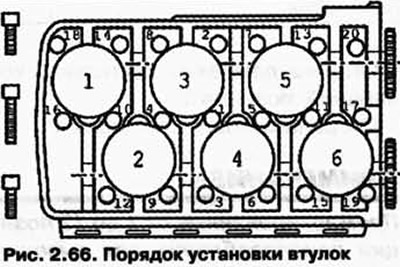
Check whether the fitted bushings are inserted in the holes 12 and 20 of the cylinder block and the head gasket is fixed (pic. 2.66).
Move the camshafts in the cylinder head to TDC 1 cyl.
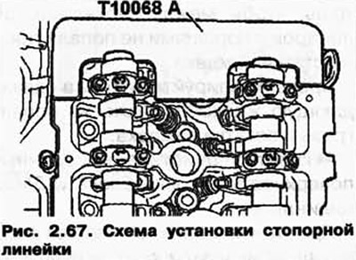
Ruler for camshafts T10068 A must be included in both grooves (pic. 2.67).
Prepare the cylinder head gasket for installation.
Install the cylinder head on the cylinder block, insert new cylinder head bolts and tighten them by hand.
Tighten the cylinder head bolts in the sequence shown in Figure 2.66 from the middle to the edges.
NOTE: The long cylinder head bolts are inserted into the middle holes in the block head.
Tighten all bolts with a pre-tightening torque of 30 Nm.
Then tighten all bolts to 50 Nm.
Then tighten all bolts 1/4 turn (90°) ordinary key.
Finally, tighten all bolts again 1/4 turn (90°).
Further installation and assembly is carried out in the reverse order of removal.
NOTE: Check if the oil port O-ring is inserted into the side cover.
Install the cylinder head cover and intake manifold.
It is not necessary to tighten the cylinder head bolts after repair work.
Check the curvature of the contact plane of the cylinder head (pic. 2.68).
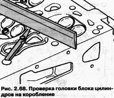
Maximum allowable curvature: 0.05 mm.
Visitor comments