
Engine cylinder head 1.8-I
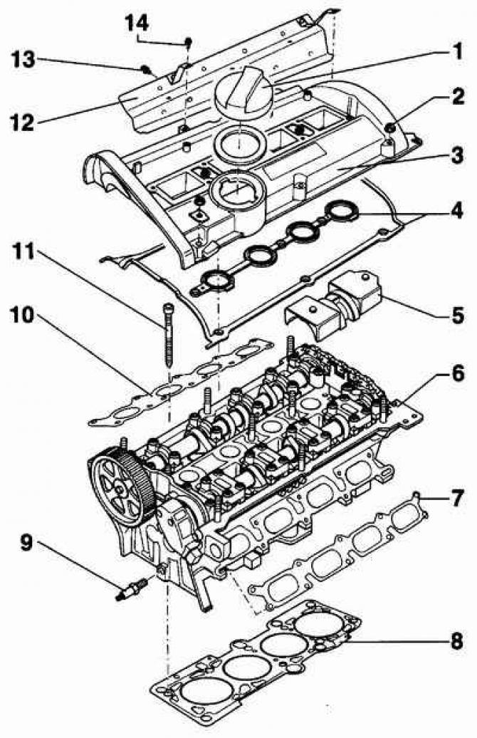
- 1 - oil filler cap,
- 2 - nut of fastening of a cover of a head of the block of cylinders, 10 Nm,
- 3 - cylinder head cover,
- 4 - gasket. When installing the gasket, apply a thin layer of sealant D2 to its surface.
- 5 - oil deflector,
- 6 - cylinder head,
- 7 - intake manifold gasket. When installing, use only a new gasket.
- 8 - cylinder head gasket. When installing, use only a new gasket. After installing the cylinder head, fill in fresh coolant.
- 9 - bolt for fastening the tension roller, 25 Nm,
- 10 - exhaust manifold gasket. When installing, a new gasket must be used.
- 11 - bolts of fastening of a head of the block of cylinders. When installing, use only new bolts.
- 12 - heat shield,
- 13 - screw, 25 Nm,
- 14 - screw, 10 Nm.
This subsection describes the operations for removing the cylinder head on a 1.6-I and 1.8-I four-cylinder gasoline engine.
Warning: Before removing the cylinder head, check that all hoses, pipes and electrical connectors are disconnected from the cylinder head.
Removal of a head of the block of cylinders make on the cold engine. The cylinder head is removed together with the exhaust manifold. In this case, the intake manifold must first be removed from the cylinder head.
A burnt or defective cylinder head gasket is determined by the following signs:
- reduction in engine power;
- decrease in coolant level. At the same time, white steam comes out of the exhaust pipe;
- decrease in engine oil level;
- the presence of coolant in the engine oil. This will increase the oil level. If there is coolant in the engine oil, the engine oil turns gray and has foam bubbles;
- the presence of engine oil in the coolant;
- intensive release of bubbles from the coolant;
- reduction of compression in two adjacent engine cylinders.
Removing
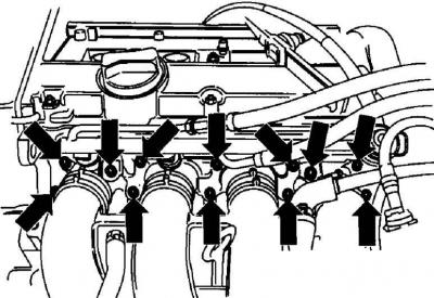
The location of the intake manifold mounting bolts on the 125 hp engine. With.
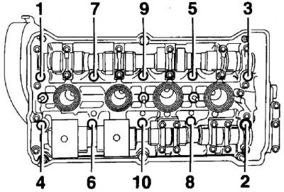
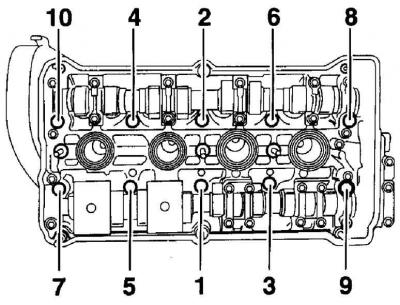
The sequence of unscrewing the cylinder head bolts
1. Check that the engine is cold. Otherwise, allow time for the engine to cool down.
2. Switch off ignition and remove a wire of weight from the accumulator.
3. Drain the coolant from the engine cooling system.
4. Mark the high voltage wires with numbers and remove the high voltage wires from the spark plugs.
5. Clean the spark plugs using a brush, vacuum cleaner or compressed air to prevent dirt from entering the engine cylinders after the spark plugs are removed. Unscrew the spark plugs using a spark plug wrench.
6. Relieve the pressure in the fuel system. To relieve pressure in the fuel system, wrap around the connection of the fuel hoses and, being careful, slowly loosen the connection, while gradually reducing the pressure in the fuel system.
7. Mark and disconnect the supply and return fuel hoses from the fuel distributor. Before disconnecting the hoses, loosen the clamp and move it to the hose.
8. After disconnection, close the ends of the pipelines with suitable plugs.
9. Disconnect the electrical connectors from the fuel injectors and move the fuel line down. Mark and disconnect from a head of the block of cylinders all electric sockets.
10. Unscrew the bracket from the cylinder head that supports the intake manifold near the fuel pressure regulator.
11. Unscrew an inlet collector from a head of the block of cylinders, see fig. The location of the intake manifold mounting bolts on the 125 hp engine. With.).
12. Unscrew the intake manifold from the two rubber mounts and move it away from the cylinder head.
13. Mark and disconnect from a head of the block of cylinders hoses of system of cooling.
14. Unscrew the exhaust pipe with catalyst from the exhaust manifold.
15. Remove the top casing of a gear belt. For the crankshaft pulley mounting bolt, turn the engine crankshaft clockwise until the alignment marks on the pulleys align with the pointers. In this case, the piston of the first cylinder will be at TDC on the compression stroke.
16. Using paint or a marker, mark the position of the crankshaft pulley in relation to the cylinder block and rotate the engine crankshaft 90°clockwise so that neither piston is at top dead center.
Before installing the toothed belt, set the crankshaft to a position in which the piston of the first cylinder is at TDC on the compression stroke.
17. In the sequence shown in fig. The sequence of unscrewing the cylinder head bolts, gradually and evenly unscrew the cylinder head bolts.
18. Check that all pipes, hoses and electrical connectors are disconnected from the cylinder head.
19. Remove the cylinder head from the engine and place it on two pieces of wood.
20. Remove the cylinder head gasket.
Preparing the head for installation
Place of measuring the height of the cylinder head
- A = 139.2 mm for 1.8 l engines
- A = 132.6 mm for 1.6 l engines
1. Remove the plastic plugs designed to protect the open cylinder head valves.
2. The mating surfaces of the head and cylinder block must be perfectly clean. Use a hard plastic or wooden scraper to clean them.
Warning: Be careful when cleaning as aluminum alloy is very easy to damage.
3. Check that carbon deposits do not get into the oil and water channels. This is especially important for the lubrication system, as deposits can block the oil supply to engine components. Clean channels if necessary.
4. Check the mating surfaces of the cylinder head and block for nicks, deep scratches or other damage. If the defects are small, they can be removed by machining.
Warning: The height of the cylinder head after machining should be 1.8L = 139.2 mm for the 1.8L engine and 132.6mm for the 1.6L engine.
5. Using a metal ruler and feeler gauge, check the flatness of the mating surfaces.
The deviation from flatness should be no more than 0.1 mm.
6. Clean the bolt holes in the cylinder block. Screwing a bolt into an oil-filled hole can rupture the block due to hydraulic pressure.
Warning: When installing the cylinder head, it is necessary to use new cylinder head bolts and a new cylinder head gasket.
Installation
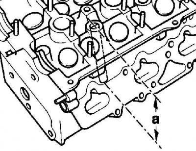
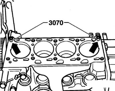
Places where the VW-3070 or VW-3450 guide pins are screwed into the engine block
Cylinder head bolt tightening sequence on four-cylinder engines
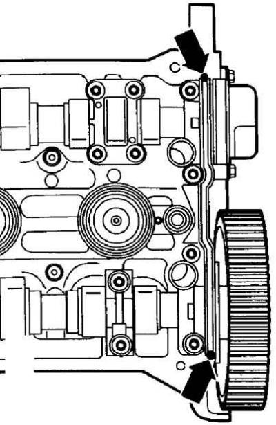
Places where D2 sealant should be applied prior to installing cylinder head cover gasket
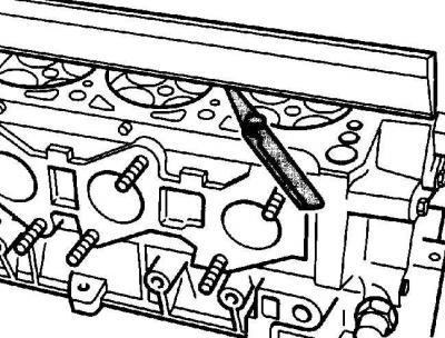
1. For the correct installation of the cylinder head and the cylinder head gasket, screw into the extreme hole of the cylinder block, designed for the cylinder head mounting bolts, the guide pins VW-3070 (for AHL VW-3450 engine). If there are no guide pins, you can make them yourself, for which you need to use two old cylinder head bolts. Cut off the head bolts and cut a slot for a screwdriver instead. After installing the cylinder head, using a screwdriver, unscrew the guide pins, see fig. Places where the VW-3070 or VW-3450 guide pins are screwed into the engine block.
Warning: When installing the cylinder head, a new gasket must be used. Remove the gasket from its sealed package just before installing it on the cylinder block.
2. Check that the new cylinder head gasket is the same type as the original and that the TOP or OBEN·markings are facing up. Position the new cylinder head gasket on the surface of the cylinder block on the guide pins. Check that the holes are correctly aligned with the channels of the cooling and lubrication system.
3. Being careful, establish a head on the block of cylinders.
4. Insert and hand tighten the 8 cylinder head bolts with washers.
5. Unscrew the two guide pins with a screwdriver and screw in the two cylinder head bolts in their place.
6. Gradually, in the sequence shown in Fig. The sequence of tightening the cylinder head bolts on four-cylinder engines, tighten the cylinder head bolts in several stages.
Warning: Do not tighten the cylinder head bolts when the engine is warm. When installing a new cylinder head with a camshaft, after installing the cylinder head, lubricate the mating surfaces of the hydraulic tappets and camshaft cams with a thin layer of grease.
7. Rotate the crankshaft and camshaft to match the position of the No. 1 cylinder piston at TDC on the compression stroke.
8. Before installing the cylinder head cover inner gasket, lubricate the gasket mating surfaces with a light coat of D2 Sealant (see fig. Places where D2 sealant should be applied prior to installing cylinder head cover gasket). Install the cylinder head cover gasket.
9. Install the cylinder head cover and gradually and sequentially tighten the cover nuts in a diagonal pattern.
10. Install the toothed belt on the camshaft pulley and adjust its tension.
11. Screw on the exhaust pipe.
12. Install the intake manifold with a new gasket on the cylinder head and secure it with bolts, tightening them to the required torque.
13. Screw the lower part of the intake manifold to the rubber-metal supports.
14. Install bracket between cylinder head and intake manifold.
15. Connect the fuel supply and return lines to the fuel line.
16. Connect all electrical connectors to the cylinder head in accordance with the markings previously made.
17. Install the toothed belt guards.
18. Check that all hoses, pipes and electrical connectors are connected as previously marked.
19. Check the engine oil level and top up if necessary. If the old cylinder head gasket was defective, change the engine oil.
20. Pour coolant into the cooling system.
21. Pour coolant into the cooling system.
22. Connect ground wire to battery.
23. Start the engine and warm it up to operating temperature. Stop the engine and check the engine oil and coolant levels and all connections for leaks.
Visitor comments