
- The engine feels nothing more than warm to the touch.
- The pistons must not be at TDC.
Removing the cylinder head
Carefully! When performing installation work, especially in the engine compartment due to its dense layout, the following rules must be observed.
- Highways of all types (fuel, hydraulic, fuel vapor recovery systems, coolant, coolant, brake fluid, vacuum) and wires should be routed in the original factory order (using appropriate fasteners).
- To avoid damage to hoses, tubes or wires, sufficient space must be provided when working on all moving or hot parts.
- Check if the car is equipped with a coded radio. In this case, request a security code.
1. With the ignition off, disconnect the battery ground wire.
2. Remove the toothed belt of the main timing drive.
3. Remove the crankcase of the distribution rooms.
4. Remove the roller arm supports with the arms and place them on a clean surface. At the same time, ensure that during the subsequent installation of the support (leverage) were in their original positions.
5. Open and close the expansion tank cap again to relieve pressure in the cooling system.
6. Then drain the coolant.
7. Loosen the spring clamps and disconnect the cooling system hoses from the thermostat housing.
3. Remove the guide tube of the oil dipstick.
Attention! The fuel supply line is under pressure! Wear safety goggles and gloves to avoid injury and skin contact with fuel. Before disconnecting the elements of the system, the connection point must be wrapped with rags. Then release the pressure by carefully disconnecting the hose.
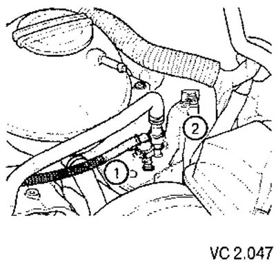
9. Disconnect the fuel supply line (2). To do this, compress the clamps.
10. To prevent contamination from entering the fuel system, plug the openings of the fuel lines.
11. Disconnect or disconnect the following parts.
- Hose from activated charcoal canister system to intake manifold.
- Vacuum hose from brake booster to intake manifold.
- Knock sensor connector (1) (G61) (on the back of the cylinder block), as well as the intake manifold pressure sensor connector (G71) with intake air temperature sensor (G42).
- Connector from engine speed sensor (G28).
- Connector from coolant temperature sensor (G62), oil pressure sensor (F1) and EGR valve (N18).
- Throttle control unit connector (J338).
- Injector connectors.
- Connector from heated vacuum valve on oil separator.
- Crankcase breather hose on intake manifold.
- Disconnect all other wires from the engine that need to be disconnected and set them aside.
12. Unscrew the front exhaust pipe from the exhaust manifold.
13. Unscrew the fixing bolt of the rear cover of the toothed belt in the area of the right hanging eye.
Attention! Both eyelets are located on the cylinder head, so an additional slinging device must be attached to suspend the engine from the cylinder block.
Engine code BCA
13. Remove the deflector roller bracket.
Continued job description for all vehicles
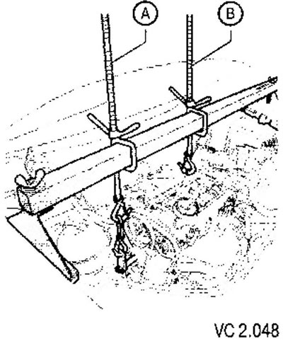
14. Screw the holder into the threaded hole of the take-off roller in the cylinder block as shown in the figure. Tightening torque: 20 Nm.
15. Second threaded rod (A) raise the engine slightly to relieve the thrust (IN).
16. Remove traction (IN).
17. Remove the bracket from the thermostat housing that secures the cooling system pipe to the coolant pump.
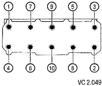
18. Loosen and unscrew the cylinder head bolts in the specified sequence.
19. Carefully remove the cylinder head.
Cylinder head installation
Attention!
- There must be no oil or coolant in the threaded holes of the cylinder head bolts located in the cylinder block. Otherwise, when tightening the cylinder head screws, the cylinder block may be destroyed.
- A new cylinder head gasket should only be removed from the packaging immediately before installation.
- The gasket must be handled very carefully.
1. Prepare new cylinder head screws.
2. Fill the cylinders with clean rags so that dirt and abrasive residues cannot get between the pistons and the cylinder surface. Also, do not allow dirt and abrasives to enter the cooling system.
3. Being careful, to clear landing surfaces of cylinder head and the block of cylinders. At the same time, do not leave scratches on the mating surfaces.
4. Carefully remove the remnants of abrasive and polishing compounds, as well as rags.
5. Bring the piston of the first cylinder to TDC and again slightly turn the crankshaft back.
6. Install a new cylinder head gasket. The inscription on the gasket (part no) while it should be visible.
7. To establish a head of the block of cylinders so that aligning plugs were established in corresponding openings.
8. Install new block head screws and tighten by hand.
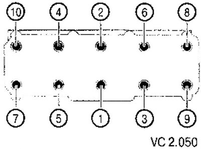
9. Tighten the cylinder head screws in the specified sequence (see fig. VC2.050) in the following way:
- tighten all screws to 30 Nm;
- tighten screws 1/4 turn (90°);
- tighten all screws 1/4 turn again (90°).
Attention: at each stage of tightening, the specified sequence must be strictly observed.
10. Install the roller lever supports in the cylinder head and install the corresponding roller levers on them and on the ends of the valve stems.
11. Install the camshaft housing.
12. Install the toothed belt of the main timing drive.
Further installation is carried out in the reverse order of removal.
Visitor comments