



- Disassembling the cylinder head.
- Checking the valve guides (replacement if necessary).
- Processing of valve seats.
- Lapping of valves.
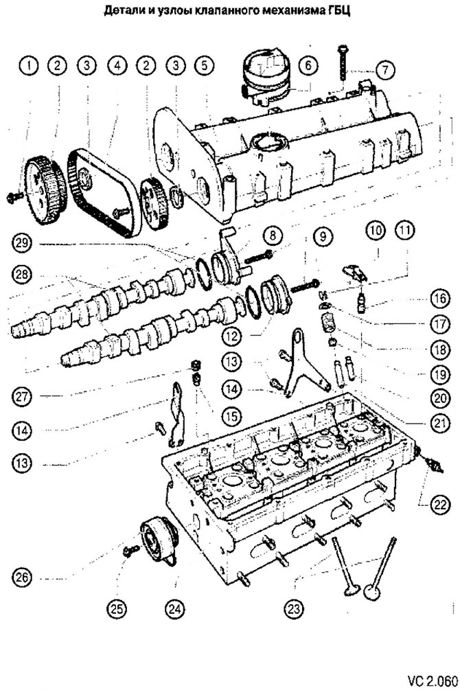
List of parts and assemblies of the cylinder head valve mechanism with technological recommendations for repair to figure VC2.080:
1. Inlet camshaft mounting screw: 20 Nm + tighten by 1/4 turn (90°):
- replace with a new one during assembly;
- use a toothed pulley lock to loosen and tighten.
2. Timing pulley of the camshaft:
- maintain the correct position when installing the timing belt.
3. Camshaft oil seal:
- replace only with the camshaft installed;
- Before installation, lightly lubricate the working edge with oil.
4. Timing belt of the coupled drive:
- Before removing, mark the direction of travel;
- check for wear;
- avoid fractures.
5. Camshaft housing:
- carefully clean the seating surfaces; they should be free of oil and grease;
- apply sealant before installation;
- when installing, install vertically from above on studs and mounting pins.
6. Oil filler neck:
- engine with letter designation BSA:
- if there is any damage, replace;
- engine with letter designation BUD:
- has only one oil filler cap.
7. Camshaft housing fastening screw: 10 Nm + tighten further by 1/4 turn (90*):
- replace with a new one during assembly;
- tighten from the center to the edges.
8. Camshaft housing end cover (intake camshaft).
9. Camshaft housing end cover fastening screw (intake camshaft): 10 Nm.
10. Rocker arm:
- check for jamming;
- lubricate the working surface;
- when installing, secure it to the support with a locking bracket.
11. Conical crackers.
12. Lid.
13. Screws for fastening the lifting eye: 20 Nm.
14. Sling eye.
15. Check valve: 6 Nm:
- do not tighten it any further, otherwise the valve may jam;
- clean the threads and install using sealant.
16. Roller lever support with hydraulic clearance compensator.
- do not swap;
- lubricate the working surface;
- Before installation, check the axial run-out of the camshaft.
17. Valve spring plate.
18. Valve spring:
- removal and installation: with the cylinder head removed, using a valve spring compressor.
19. Valve stem seals.
20. Valve guide repair bushing with flange.
21. Valve guide sleeve.
22. Oil pressure sensor (F1): 25 Nm.
23. Valves:
- cannot be processed by cutting or grinding, only lapping is allowed.
24. Cylinder head.
25. Timing belt tension roller fastening screw: 20 Nm.
26. Tension roller of the mating belt drive.
27. Locking screw:
- the maximum permissible screw-in depth when measured from the contact surface with the camshaft housing is 2 mm.
28. Camshafts:
- lubricate with oil before installation (including the thrust bearing surface);
- replace the seals after installation.
29. End cap sealing ring:
- replace with a new one during assembly.
Visitor comments