
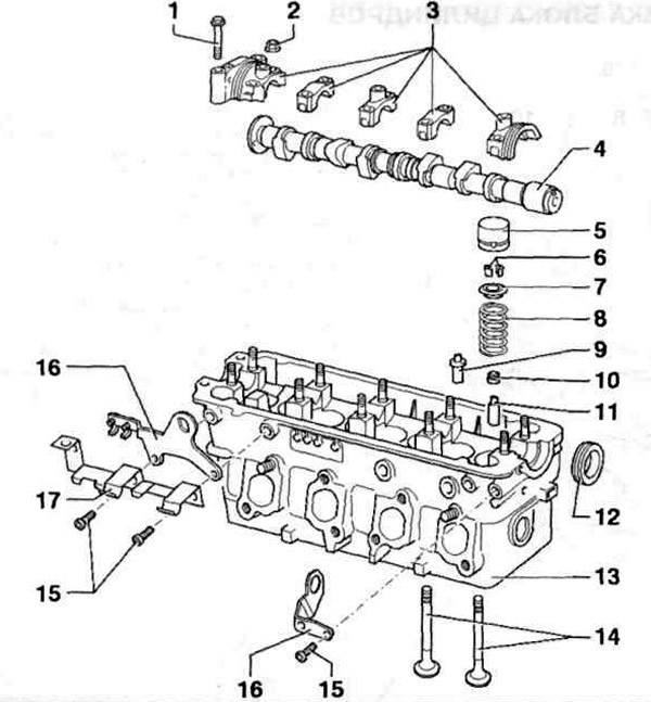
Pic. 3.13 a. Elements of the gas distribution mechanism:
1, 15 - Bolts; 2 - Nut; 3 - Root covers of the camshaft; 4 - Camshaft; 5 - Hydraulic compensator; 6 - Crackers; 7 - Upper spring plate; 8 - Valve spring; 9 - Valve guide with collar; 10 - Valve stem seal; 11 - Valve guide sleeve; 12 - Camshaft seal; 13 - Cylinder head; 14 - Valves; 16 - Lifting eye; 17 - Bracket.
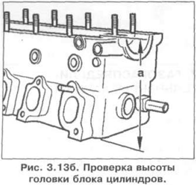
Checking the height of the cylinder head is shown in fig. 3.13 b. Cylinder head height: 135.6 mm.
Checking the axial clearance of the camshaft using an indicator is carried out with the hydraulic compensators removed and cover No. 3 installed and is shown in fig. 3.13 c.
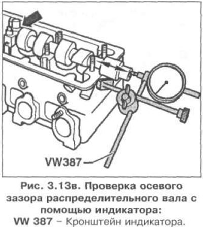
Permissible axial clearance: 0.15 mm.
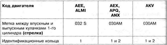
Camshaft identification is shown in fig. 3.13
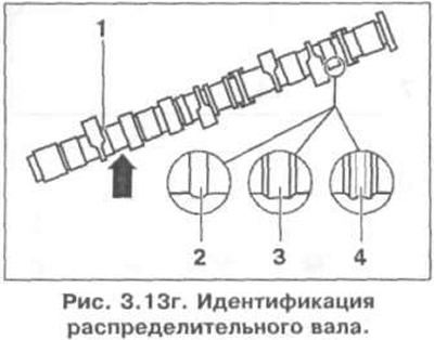
Camshaft identification
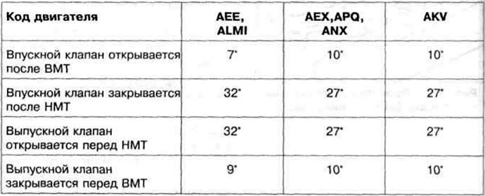
Valve timing at 1 mm valve lift
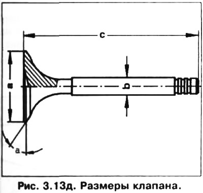
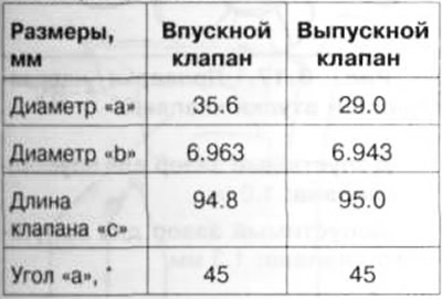
Valve dimensions are shown in fig. 3.13 d.
Valve dimensions
Visitor comments