



Contents: Removal ↓ Installation ↓
Rear wheel brake mechanism
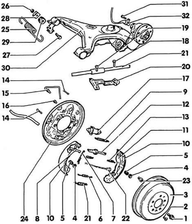
1. Wheel bolt, 160 Nm; 2. Hexagon socket head cap screw, 5 Nm; 3. Brake drum; 4. Spring plate; 5. Pressure spring; 6. Lower return spring; 7. Tension spring; 8. Adjustment lever; 9. Upper return spring; 10. Brake shoe with lining; 11. Brake lever; 12. Push rod with adjusting gear; 13. Return spring; 14. Locking pin; 15. Brake pipe; 16. Screw, 19 Nm; 17. Brake cylinder; 18. Screw, 7 Nm; 19. Self-tapping screw, 7 Nm; 20. Handbrake cable bracket; 21. Lower return spring; 22. Handbrake cable; 23. Hexagon socket head cap screw; 24. Brake support; 25. Brake force regulator spring; 26. Hexagon nut, 20 Nm; 27. Screw; 28. Locking plate; 29. Holder; 30. Steering knuckle; 31. Screw, 10 Nm; 32. ABS speed sensor
Removal
1. Loosen the front wheel mounting bolts. The car stands on its wheels.
2. Mark the position of the disc relative to the wheel hub with paint so that you can then install the balanced wheel in its original position.
3. Place the car on jacks and remove the wheel.
4. Unscrew the 2 brake mechanism screws from the wheel bearing housing and remove the brake mechanism and brake support assembly.
5. If necessary, unscrew the brake hose brackets from the wheel bearing housing.
6. Hang the brake mechanism on a homemade wire hook to the body so that the brake hose is not twisted or stretched.
Attention! Do not remove the brake hose, otherwise you will need to bleed air from the system.
7. If the brake mechanism needs to be removed completely, the brake hose must first be unscrewed from the brake hose connection, not from the brake mechanism.
Warning! Brake fluid leakage. Collect the fluid in a container intended only for brake fluid. You can first suck the brake fluid out of the expansion tank with a rubber bulb.
8. Remove the brake disc mounting screw using a 5mm Allen key.
9. Remove the brake disc.
Warning! The brake disc must not be removed using brute force (hammer blows) from the wheel hub. Instead: use a rust remover. This will prevent damage to the brake disc. If removal is only possible by strong hammer blows, replace the brake disc and wheel bearing for safety reasons. Wheel bearing replacement should be entrusted to a service station, as this is usually the only place where the appropriate press is available. Even if the appropriate puller is used, the brake disc must be replaced.
Installation
1. In order to ensure uniform braking on both sides, both discs must have equally ground surfaces. Therefore, both brake discs must be replaced or both must be ground.
2. The plant has the ability to check brake discs for wear. The maximum allowable wear measured on the braking surface is 0.03 mm. The maximum allowable thickness deviation is 0.01 mm.
3. Measuring the thickness of the brake disc (see subsection 7.5).
4. If there is any, remove rust from the brake disc flange and front wheel hub, lubricate with a thin layer of grease.
5. Clean new brake discs with nitro solvent to remove protective varnish.
6. Install the brake disc onto the wheel hub and secure with the Allen screw.
7. Install the brake mechanism together with the installed brake pads. Do not twist or stretch the brake hose. Check the free play of the brake hose by turning the steering wheel until it stops.
8. Screw the brake hose bracket to the end of the wheel bearing.
9. Tighten the brake mechanism to a torque of 270 Nm.
Warning! High torque, use a strong tool. When tightening, make sure that the machine does not slip off the trestles. Set the tool so that when tightening, press the handle down.
10. If the expansion tank is empty or the brake hose has been removed, screw on the brake hose and bleed the air from the system (see subsection 7.12).
11. Install the wheel according to the marking and remove the car from the stands and tighten the bolts crosswise to a torque of 160 Nm.
Attention! Press the brake pedal vigorously and repeatedly until you feel noticeable resistance.
12. Check the brake fluid level in the expansion tank (see subsection 7.13).
Attention! Lubricate the thread of the pressure rod, the contact surfaces of the brake pads to the brake support, the ribs of the brake pads in the supports, and the brake lever with a light layer of Molykote G6 paste.
13. Replace brake pads only on both wheels of the same axle. Use brake pads of the same quality.
Visitor comments