
English Русский
Български
Беларускі
Український
Српски
Hrvatski
Română
Polski
Slovenský
Magyar
  |  Articles  |  Sitemap  |  Contacts  |    |
Car maintenance Ford Car maintenance Hyundai Car maintenance Chevrolet Car maintenance BMW Car maintenance Audi Car maintenance Opel Car maintenance AvtoVAZ
VWmanual.ru


Main   Passat   Golf   Polo   Touareg   Tiguan   Sharan   Transporter   Others  
Transporter T3 (1979-1992) Transporter T4 (1990-2003)

Brake pads — removal and installation (VW Transporter T4)

  • Main
  • Transporter
  • Transporter T4
  • Chassis
  • Brake system
  • Brake pads — removal and installation
            0


Contents: Removal ↓ Installation ↓
The rear wheel drum brakes are adjusted automatically. The pressure rod changes its position under the influence of the adjusting device and ensures a constant, structurally determined gap between the brake drum and the shoes.

For automatic adjustment, the pressure rod has a thread on which a gear sits. By rotating, the gear changes the position of the pressure rod. After pressing the brake pedal once, a gap is provided between the brake drum and the brake shoes.

If the brake shoe movement, as a result of brake lining wear, is greater than the specified clearance, the gear, under the influence of the adjusting lever and spring, rotates further by one tooth. The position of the pressure rod changes - the brake shoes are adjusted automatically.

Attention! Special pliers for brake springs, such as HA2ET 797, are best suited for removing springs. You can also use a gas wrench.


Removal


The order of removing springs
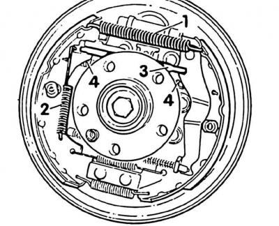


The order of removing springs


1. Remove the brake drum.

2. Remove the return spring (1). Remove the spring (2) of the adjusting lever. Use a screwdriver to completely unscrew the adjusting gear of the pressure rod (3) back. Remove the return spring (4) – see Fig. Procedure for removing springs.
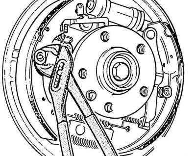


2. Remove the return spring (1). Remove the spring (2) of the adjusting lever. Use a screwdriver to…


(The article is posted on the portal: «VWMANUAL»)

3. Press hard with a gas wrench on the pressure spring plate and turn it 90° (1/4 turn). While pressing, hold the pin on the back of the brake support.

4. Remove the second spring plate.
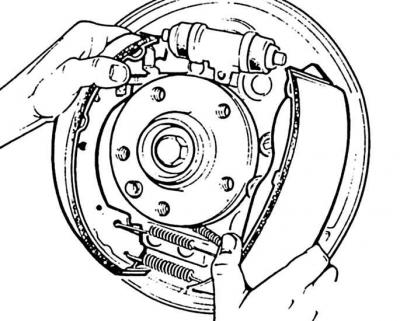
4. Remove the second spring plate.


5. Spread the brake pads from above with your hands and remove them.

6. Remove the lower return springs.
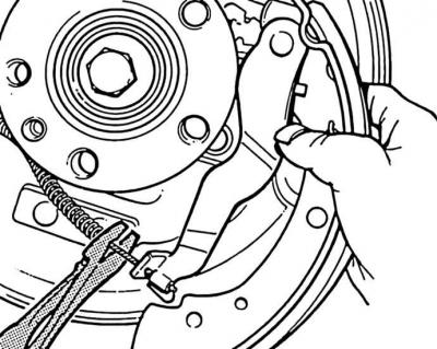
6. Remove the lower return springs.


7. Disconnect the handbrake cable.


Installation


Spring installation procedure
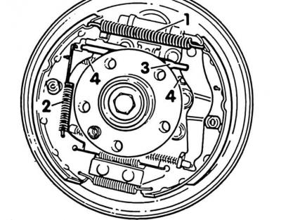


Spring installation procedure


1. Install brake linings of only one quality. Clean the brake shoes and brake support. When the brake shoes are removed, do not press the brake pedal, otherwise the piston will slip out of the brake cylinder. If the brake cylinder is damp, overhaul it. Clean the thread of the pressure rod and lubricate. Clean the drums with traces of grooves. Always grind both drums of the axle.

2. Apply a thin layer of Malykote G6 paste to the threads of the pressure rod, the mating surfaces of the brake pads to the brake support, the ribs of the brake pads in the supports and the brake lever on the brake lever.

3. Place the handbrake cable on the brake shoe.

4. Install the lower return spring and place the brake shoes on the lower support.

5. Install the pressure rod with the adjusting gear on top between the brake shoes.

Note! The left rear wheel push rod has a right-hand thread, the right rear wheel has a left-hand thread. The bevel of the sleeve and the long journal on the push rod point to the brake support shield.


6. Install the brake pads onto the brake cylinder piston.

7. Insert the pressure spring pins from the rear through the brake shoes.

8. Install the compression springs. Install the spring plates with combination pliers and compress the spring while holding the pin at the back (see fig. Spring installation order).

9. Turn the spring plate 90° (1/4 turn) and stop.

10. Install the return springs in the sequence 4, 2, 1.

11. Perform basic adjustment of the rear wheel brakes.

12. Install the brake drum (see subsection 7.7).

13. Press the foot brake repeatedly and firmly. This will adjust the rear wheel brakes.

14. Install the wheel, paying attention to the markings. Remove the car from the jacks and tighten the bolts crosswise to 160 Nm.

15. Adjust the handbrake.

16. Check braking at medium speed. If the car pulls to one side during braking, determine the cause and eliminate it (see subsection 7.19).

This article is available at russian, bulgarian, belarusian, ukrainian, serbian, croatian, romanian, polish, slovak, hungarian
The text has been checked: Orlov Dmitry

Share information:

Previous articles
Brake drum — removal and installation
Brake disc and brake mechanism — removal and installation
Checking the thickness of brake discs
Eliminating squeaks from disc brakes
Front disc brake pads (15-inch wheels)
Front disc brake pads (14-inch wheels)
Next articles
Basic rear wheel brake adjustment
Adjusting the handbrake
Brake fluid
Bleeding the brake system
Replacing brake fluid
Wheel brake cylinder — removal and installation


Similar articles from other manuals for VW cars:
Removal and installation front disc brake pads VW II Passat B3 (1988-1993)
Replacing rear drum brake pads Golf 1 (1974-1984, petrol)
Removal and installation of brake pads and brake caliper up to… Polo 3 (1995-2003)
Adjusting brake pads on two wheels Touareg 1 (2002-2006)
Removal and installation front brake pads FN 3 Tiguan 1 (2007-2015)
Checking the thickness of the front brake pads Sharan 1 (1995-2000)
Checking the thickness of disc brake pads Caddy 3 (2003-2010)
Link to this page in different formats


Visitor comments


No comments yet


How much will 47 + 13 =


Transporter T4 
  • General information
  • User manual
  • Maintenance
  • Power unit
  • Engine repair
  • Ignition system
  • Lubrication system
  • Cooling system
  • Fuel system (petrol)
  • Fuel system (diesel)
  • Injection system (petrol)
  • Exhaust system
  • Transmission
  • Clutch
  • Car gearbox
  • Chassis
  • Car suspension
  • Steering
  • Brake system
  • Wheels and tires
  • Body
  • Exterior
  • Interior
  • Doors and windows
  • Heating system
  • Electrical equipment
  • Equipment and devices
  • Lighting and signaling
  • Power devices
  • Electrical circuits
Transporter T3 
  • General information
  • Maintenance
  • Petrol engines
  • Engine repair
  • Lubrication system
  • Cooling system
  • Power and exhaust system
  • Carburetor 34 PICT
  • Carburetors 2E3 and 2E4
  • Fuel injection system
  • Ignition system
  • Diesel engines
  • Engine repair
  • Lubrication system
  • Cooling system
  • Power and exhaust system
  • Transmission
  • Clutch
  • Car gearbox
  • Chassis
  • Front suspension
  • Rear suspension
  • Steering
  • Brake system
  • Body
  • Body and interior elements
  • Doors, locks and windows
  • Electrical equipment
  • Lighting system
  • Equipment and devices
  • Power devices (diesel)
  • Power devices (petrol)
  • Wiring diagrams (diesel)
  • Wiring diagrams (petrol)
VWmanual.ru © 2016-2026 | Mobile version | News and articles | Sitemap: EN BG BY UA RS HR RO PL SK HU | Write message | Site search
Passat B2 • Passat B3 • Passat B4 • Passat B5 • Passat B6 • Golf 1, diesel • Golf 1, petrol • Golf 2, petrol • Golf 2 • Golf 3 • Golf 4 • Golf 5 • Polo 3 • Polo 4 • Touareg 1 • Tiguan 1 • Sharan 1 • Transporter T3 • Transporter T4 • LT 28 • LT 2D • Beetle • Caddy 3 •
Our website uses cookies to ensure functionality and convenience.