
English Русский
Български
Беларускі
Український
Српски
Hrvatski
Română
Polski
Slovenský
Magyar
  |  Articles  |  Sitemap  |  Contacts  |    |
Car maintenance Ford Car maintenance Hyundai Car maintenance Chevrolet Car maintenance BMW Car maintenance Audi Car maintenance Opel Car maintenance AvtoVAZ
VWmanual.ru


Main   Passat   Golf   Polo   Touareg   Tiguan   Sharan   Transporter   Others  
LT 28 (1975-1991) LT 2D (1996-2003) Beetle (1960-1986) Caddy 3 (2003-2010)

Notes on the specifics of cylinder head disassembly and assembly work (VW Caddy 3)

  • Main
  • Volkswagen
  • Caddy 3
  • Petrol engines 1.4 l
  • Engine repair
  • Notes on the specifics of cylinder head disassembly and assembly work
            0


Contents: Removal and installation the…↓ Installation ↓

Removal and installation the camshaft housing


Attention!
  • In this engine, the camshafts are located in the camshaft housing. Therefore, it is only permitted to remove the camshaft housing after first removing both timing belts.
  • The seating surface of the camshaft housing must not be machined.


For engines with the letter designation BSA


1. Remove the air filter housing.

For engines with the letter designation BUD


1. Unscrew the screws (arrows) and remove the cover from the camshaft bearing housing.
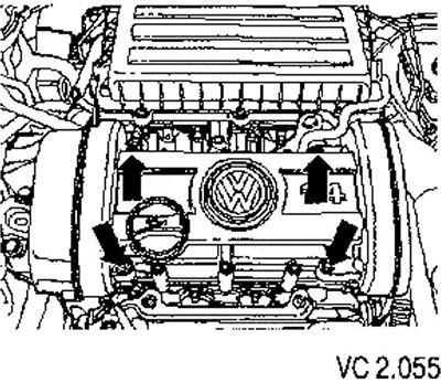
1. Unscrew the screws (arrows) and remove the cover from the camshaft bearing housing.


Continuation of the description of works for all vehicles


2. Remove both timing belts.

3. Unscrew the ground cable from the camshaft housing (arrow).
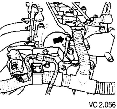
3. Unscrew the ground cable from the camshaft housing (arrow).


For engines with the letter designation BSA


4. Remove the oil filler neck.


Continuation of the description of works for all vehicles


5. Remove the ignition coils.

6. Remove the wiring box with the wiring harness from the camshaft housing.

7. Remove the cooling system ventilation pipe from the camshaft housing..

8. Disconnect the connector from the camshaft position sensor.

9. Unscrew the fastening bolt of the rear cover of the toothed belt in the area of the right lashing eye for.

10. Loosen and unscrew the camshaft housing mounting screws from the edges to the center, alternating crosswise.

11. Carefully lift the camshaft housing.

Installation


Conditions:
  • The pistons should not be at TDC.
  • The camshaft timing pulleys are secured with a camshaft locking tool through calibrated holes in the camshaft housing and are protected from turning.
  • Any remaining sealant must be removed from the cylinder head and camshaft housing using a standard sealant remover.
  • Avoid getting dirt and sealant residue into the cylinder head.
  • The seating surfaces must be thoroughly cleaned. There should be no traces of oil left on them.

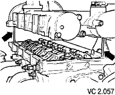
1. Apply the sealant to the clean seating surface of the camshaft housing in a thin, uniform bundle (see the shaded area in the figure VC 2.057).

Caution! The sealant layer (bead) should not be too thick, otherwise excess sealant may get into the lubrication channels, which will lead to engine damage.


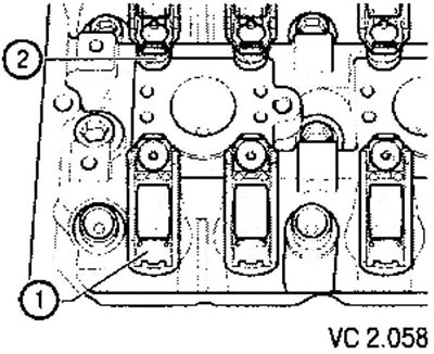
The roller lever must lie correctly on the end of the valve stem (1) and must be secured to the corresponding support (2) with a clamp.
The roller lever must lie correctly on the end of the valve stem (1) and must be secured to the…


2. Before installing the camshaft housing, screw two spacer screws (M6x70) into the cylinder head.


3. Carefully install the camshaft housing vertically from above onto the spacer bolts and cylinder head mounting pins (arrows).
3. Carefully install the camshaft housing vertically from above onto the spacer bolts and cylinder…


Caution! Do not allow oil to come into contact with the applied sealant layer.


4. Tighten the new camshaft housing mounting screws evenly in a crisscross pattern, alternating from the center to the edges. In this case, you need to ensure that the camshaft housing does not become warped.

Tightening torque: 10 Nm + tighten by 1/4 turn (90°).

Caution! After installing the camshaft bearing housing, allow the sealant to cure for approximately 30 minutes.


5. Further installation is carried out in the reverse order of removal.

For engines with the letter designation BUD


Tightening torque of the screws (arrows) securing the cover to the camshaft bearing housing: 10 Nm.
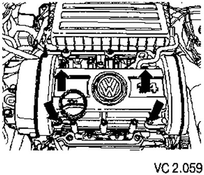
Tightening torque of the screws (arrows) securing the cover to the camshaft bearing housing: 10 Nm.

This article is available at russian, bulgarian, belarusian, ukrainian, serbian, croatian, romanian, polish, slovak, hungarian
The text has been checked: Kolesnikov Artem

Share information:

Previous articles
Checking the deformation of the cylinder head mating plane
Disassembly and assembly of the cylinder head
Removal and installation the cylinder head
Checking pistons and cylinders
Checking the clearance between the piston ring and the groove in the axial direction
Checking the thermal clearance in the joints of piston rings
Next articles
Valve mechanism repair
Fixing both camshaft toothed pulleys
Processing of the cylinder head seating surface
Camshaft — checking endplay
Valve seat machining


Similar articles from other manuals for VW cars:
Removal and installation the cylinder head Passat B3 (1988-1993)
Work on the cylinder head Golf 3 (1991-1997)
Cylinder head Polo 3 (1995-2003)
Removal and installation cylinder head covers and gaskets Touareg 1 (2002-2006)
Cylinder head Tiguan 1 (2007-2015)
Cylinder head repair Sharan 1 (1995-2000)
Removal and installation the cylinder head (petrol 4-cylinder) Transporter T4 (1990-2003)
Link to this page in different formats


Visitor comments


No comments yet


How much will 20 + 27 =


Caddy 3 
  • General information
  • User manual
  • Daily care
  • Maintenance
  • Petrol engines 1.4 l
  • Engine repair
  • Cooling and lubrication system
  • Power and exhaust system
  • Petrol engines 1.6 l
  • Engine repair
  • Cooling and lubrication system
  • Power and exhaust system
  • Diesel engines
  • Engine repair
  • Cooling and lubrication system
  • Power and exhaust system
  • Transmission
  • Mechanical gearbox 0AH
  • Mechanical gearbox 0A4
  • Drive shafts
  • Chassis
  • Car suspension
  • Steering
  • Brake system
  • Body and wiring diagrams
  • Interior and exterior
  • Electrical circuits
Beetle 
  • General information
  • Maintenance
  • Power unit
  • Engine repair
  • Cooling and lubrication system
  • Supply system
  • Exhaust system
  • Transmission
  • Clutch
  • Car gearbox
  • Chassis
  • Front suspension
  • Rear suspension
  • Steering
  • Brake system
  • Wheels and tires
  • Body
  • Exterior
  • Electrical equipment
  • Equipment and devices
  • Power devices
  • Electrical circuits
LT 2D 
  • General information
  • User manual
  • Maintenance
  • Power unit
  • Petrol engines 2.3 l
  • Diesel engines 2.5 l
  • Diesel engines 2.8 l
  • Injection system (diesel 2.8 l)
  • Transmission
  • Clutch
  • Manual gearbox
  • Differential
  • Chassis
  • Car suspension
  • Steering system
  • Brake system
  • Body
  • Body elements
  • Heating system
  • Electrical equipment
  • Equipment and devices
  • Electrical circuits
LT 28 
  • General information
  • Maintenance
  • Power unit
  • Petrol engines 2.0L
  • Petrol engines 2.4L
  • Diesel engines
  • Cooling and heating
  • Fuel and exhaust system
  • Ignition system
  • Transmission
  • Clutch
  • Car gearbox
  • Cardan shaft
  • Rear axle
  • Chassis
  • Brake system
  • Car suspension
  • Steering system
  • Body
  • Body elements
  • Doors, locks and windows
  • Electrical equipment
  • Power devices
  • Equipment and devices
  • Electrical circuits
VWmanual.ru © 2016-2026 | Mobile version | News and articles | Sitemap: EN BG BY UA RS HR RO PL SK HU | Write message | Site search
Passat B2 • Passat B3 • Passat B4 • Passat B5 • Passat B6 • Golf 1, diesel • Golf 1, petrol • Golf 2, petrol • Golf 2 • Golf 3 • Golf 4 • Golf 5 • Polo 3 • Polo 4 • Touareg 1 • Tiguan 1 • Sharan 1 • Transporter T3 • Transporter T4 • LT 28 • LT 2D • Beetle • Caddy 3 •
Our website uses cookies to ensure functionality and convenience.