
Removing the cylinder head cover
Remove the crankcase breather hose.
Remove the cover from the three fixing nuts.
Unscrew the nuts and remove the washers and gasket underneath.
Place the parts next to the exposed cylinder head.
Carefully remove cylinder head cover. If she sits firmly, then to release, knock with a hammer handle.
Replace the rubber gasket on the cylinder head cover only if damaged.
Removing the camshaft
If the camshaft is removed from the removed cylinder head, then in addition to the already mentioned work on removing the toothed belt, the adjustment of the injection pump injection moment is added.
Set the first cylinder to TDC.
Remove the camshaft gear.
Number the camshaft bearing caps with a punch or chalk strokes (for correct installation).
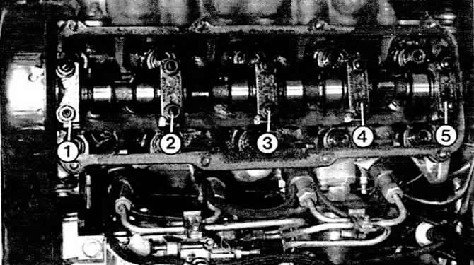
Remove bearing caps numbers 1, 3 and 5.
Loosen the nuts of the bearing caps 2 and 4 alternately crosswise.
Pull out the camshaft.
To install, lubricate all moving parts.
Insert the camshaft so that the cams of the first cylinder simultaneously point up.
First install bearing caps 2 and 4.
Caution: The bearing bore is not in the middle. Therefore, pay attention to the installation location.
Tighten nuts crosswise to 20 Nm.
Install remaining bearing caps (torque 20 Nm).
Warning: The engine must not be started for the next 30 minutes. Released from the load, the hydraulic pushers are squeezed out by their springs to the position of maximum tension. This causes the valves to open so far on the first revolution of the camshaft that they collide with the pistons. After a half-hour wait, the pressure in the hydraulic pushers decreases. To be sure, the engine must be cranked twice by hand in order to be sure that the pistons cannot collide with the valves.
Hydraulic pusher
In general, valve knocking on a vehicle with a hydraulic valve clearance adjuster indicates one or more bad hydraulic tappets. The corresponding pusher in this case is not repaired, but must be replaced.
Valve noise can also appear with serviceable hydraulic pushers, including when:
- Immediately after the launch, the oil supply of the pusher has not yet occurred.
- The car was operated in a harsh manner at high ambient temperatures for a short time before launch and the oil became more fluid.
- The car has not been used for a long time. The knock should disappear after reaching the operating temperature.
Search for a defective hydraulic pusher
Warm up the engine and let it run until the cooling fan is switched on for the first time.
Raise the speed to 2800 rpm and maintain them for about two minutes.
If the valve noise persists, turn off the engine and remove the cylinder head cover.
Set the cylinder to TDC. The camshaft lobes must point upwards.
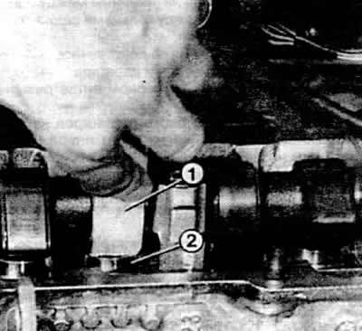
Press the hydraulic pusher to be checked using a wooden or plastic object (by no means metallic).
If the pusher moves more than 0.1 mm, then it must be replaced.
Attention: The knocking noise of the hydraulic pushers may be due to a defective cylinder head gasket - in this case, exhaust gases enter the oil system.
Removing the hydraulic pusher
Remove camshaft.
Tag Pushers (you can use a felt-tip pen) so that when you install them, you can install them in the same order.
Pull the pusher up.
Lay the tappet on a clean rag with the side facing the camshaft down so that no oil flows out.
After installing a new or unloaded pusher, the engine should not start for 30 minutes.
This is done to prevent the valves from hitting the pistons.
Removing the cylinder head
In addition to special tools for removing the toothed belt, a cylinder head gasket of the required thickness and a set of new bolts for the cylinder head are also used. Bolts with an internal polyhedron on a diesel engine must be replaced.
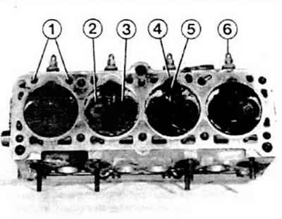
1 - coolant channels
2 - one of the exhaust valves
3 - one of the intake valves
4 - vortex chamber insert
5 - hole «shuss» -channel
6 - glow plug
Remove ground wire from battery.
Drain the coolant into a suitable container.
Remove the suction hose from the air filter housing.
Remove the cylinder head cover.
Remove the high pressure fuel pipes and place them on a clean rag.
Close the holes of the nozzles and on the injection pump with plugs (made of plastic or, in extreme cases, of paper).
Remove return line (excess fuel pipes) from injectors to injection pump.
Disconnect wires from glow plugs.
Remove plug from oil switch and temperature sensor.
Disconnect the exhaust pipe from the exhaust manifold.
Remove toothed belt.
Remove the coolant hoses from the cylinder head.
Bend aside the cold start accelerator rod.
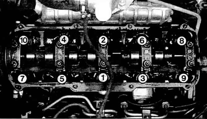
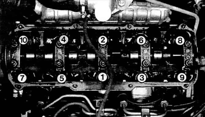
Loosen the cylinder head bolts in the reverse order of that shown in fig. To do this, the engine must be cold so that the warm cylinder head can be taken after removal.
Raise the cylinder head together with the intake and exhaust pipes. If it does not go easily, then help with light blows of a plastic hammer.
Remove the old cylinder head gasket.
Checking the cylinder head
The mating surfaces of the cylinder block and cylinder head must be absolutely clean and free of gasket residue.
Do not scratch the soft surfaces of the cylinder head seal with a hard tool. Notches can cause subsequent damage to the cylinder head gasket.
Check for cracks between valve seats or between valve seat rings and nozzle threads.
Minor scratches, not wider than 0.5 mm, or when cracks are only on the first thread of the injectors, do not affect the durability of the engine.
Check the cylinder head for distortion, especially when gaskets have been damaged due to overheating.
Lay a long metal ruler or guaranteed straight metal angle along the cleaned plane of the cylinder head.
Check with a feeler gauge that the gap between the plane and the ruler is no more than 0.1 mm.
We do not recommend regrinding the cylinder head. If the clearance is larger, the head must be replaced.
Installing the cylinder head
Now you must select the correct thickness of the cylinder head gasket, as indicated earlier.
The threads on the cylinder head bolts and in the bolt holes must be clean and undamaged, otherwise the correct torque cannot be achieved when tightening the bolts.
There must be no oil or water in the bolt holes on the cylinder block, otherwise the metal in the threaded area may break.
Turn the crankshaft so that the pistons are not at TDC, otherwise the open valve may collide with the piston when the head is seated.
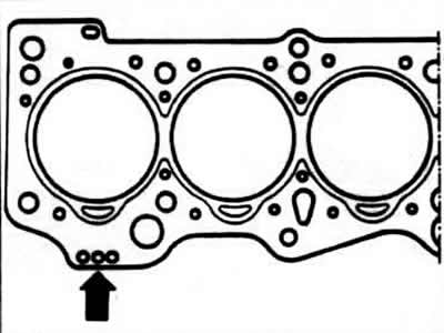
Lay the cylinder head gasket on the cylinder block so that the symbol "top" was directed towards the cylinder head.
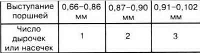
According to the number of holes or notches in the place indicated by the black arrow, the thickness of the cylinder head gasket used can be determined. The connection is given in the table below.
Install the cylinder head. To do this, two guide bolts are screwed in the factory into the bolt holes 8 and 10 when the cylinder block no longer has dowel pins for the cylinder head gasket. The connection is given in the table below.
Install the cylinder head. To do this, two guide bolts are screwed at the factory into the bolt holes 8 and 10, when the cylinder block no longer has centering pins for the head gasket.
Temporarily, two metal rods with the thickness of the cylinder head bolts will also work. Without aids, the gasket and head will definitely move during installation.
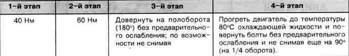
Screw in the cylinder head bolts and then tighten with a cold engine according to the tightening diagram and the tightening torque given in the table below.
Install the rest of the parts in the reverse order of removal.
Attention: If the cylinder head was removed due to gasket damage, the coolant must be completely replaced. The same must be done when installing a cylinder head purchased in exchange.
Cylinder head tightening torques
Choosing the right cylinder block gasket
Diesel engines are fitted with cylinder head gaskets of various thicknesses. Their thickness depends on whether the pistons used in this engine have technological deviations at the top or bottom. Since the cylinder head gasket is located between the cylinder block and the cylinder head, it is possible, by choosing its thickness, to vary the height of the combustion chamber and thus equalize the differing heights of the pistons. The thickness of the gasket is given by the number of small holes or notches on the side of the gasket shown in fig. Holes or notches are visible from the outside on an already installed block head.
If only the cylinder head is replaced on the engine, or the old head is removed and then installed, then you can buy a new gasket just like the old one, i.e. with the same number of holes or notches. If parts of the piston group are replaced (crankshaft, connecting rods, pistons) or the entire cylinder block is replaced, the piston protrusion must be re-measured. This is a measure of how far the pistons protrude from the cylinder block. According to the table, the required gasket is selected.
Visitor comments