
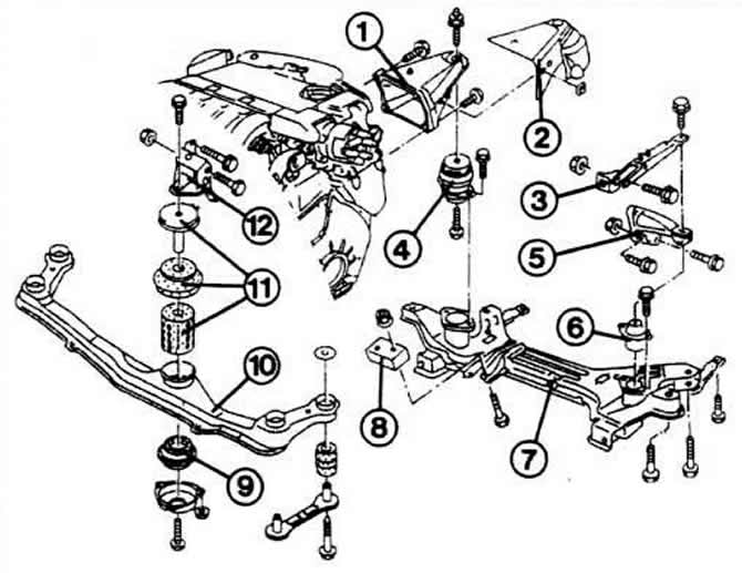
1 - right engine console
2 - casing (not installed on our models)
3 - gearbox support
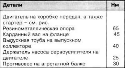
4 - rubber-metal support
5 - left gearbox console
6 - rubber-metal support
7 - aggregate beam
8 - counterweight
9 - rubber-metal support
10 - engine beam
11 - rubber-metal support
12 - front console of the engine
The engine is pulled up along with the gearbox. To do this, you will need a lift that you can stably hang at the required height.
It is recommended to carry out this work with an assistant. Before work, look at the picture of the engine compartment so that you know where the described parts are.
Since in the model «Golf» a large number of electrical wires and vacuum hoses are installed, you must first mark all their connections in order to install them correctly.
Removing
Remove the battery.
Remove the engine hood.
On vehicles with air conditioning, do not open the coolant line!
Since the compressor is removed in the presence of an air conditioner, it is necessary to fix it together with closed hoses on the front side of the car so that the hoses are not under tension.
Unscrew air conditioner fluid reservoir and let it hang freely.
Remove the front of the car. If there is an air conditioning system, the front of the car must be laid on the longitudinal beam behind the coolant hoses and reinforced with wire to prevent rolling.
Remove the air filter housing together with the suction hoses at the front and rear from the engine.
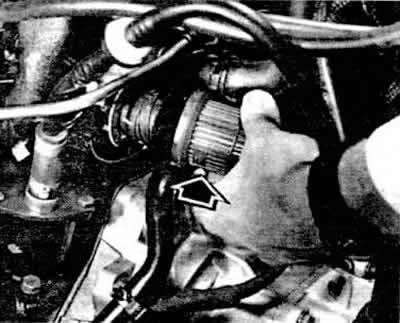
Disconnect the central motor connector. To do this, hold the narrow part of the plug (arrow) and turn the wide ring.
Disconnect the cable plugs at the reversing light switch and at the tachometer sender.
Unscrew the earth connections on the gearbox and pull it out.
Hang the gas draft on the injection pump lever and on the stop. insert the protective cover into the notch again (retains alignment when assembled).
Disconnect the cold start acceleration link from the injection pump.
Close the connection point on the injection pump again with a wooden plug.
Remove hose between vacuum pump and brake booster.
Disconnect the clutch rod from the lever and set aside.
Loosen the two bolts on the servo pump tensioner.
Loosen the three pivot arm mounting bolts and remove the V-belt.
Set the power steering pump aside with the plugged hoses.
Drain coolant.
Disconnect all coolant hoses between radiator, heat exchanger, engine and expansion tank.
On vehicles with automatic transmission, remove the notched V-belt.
Remove shock absorber and water pump pulley.
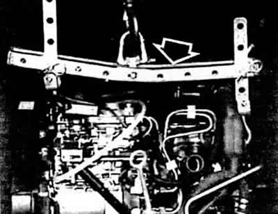
Stop the car in front.
Remove shift bar and short shift bar. To do this, on the long rod on the left in the direction of travel, pull the clamping lever on the plastic head with a screwdriver, pull the hose away from the head.
On an automatic transmission, set the shift lever to position «R», remove the rod from it from the gearbox.
Unscrew the driveshafts of the front wheel drive to the right and left of the gearbox and tie them to the body with wire.
Unscrew the counterweight from the aggregate beam.
If present, unscrew the heat shield for the inner joint of the right cardan field.
Unscrew the exhaust pipe from the exhaust manifold.
«let go» automobile.
Disconnect the ABS sensor connector on the right engine console (anti-lock brake system).
Unscrew the bolt between the right engine console and the rubber-metal support.
Release the gearbox console from the rubber-metal support.
Slightly raise the engine/gearbox assembly (power unit).
Remove crankcase.
Unscrew the bolt from the top of the front rubber-metal support.
Pass two chains or suitable steel cables through the axles on the right and left of the engine and attach them to the hoist.
Unbolt gearbox supports and brackets.
Turning slightly, carefully pull out the power unit.
When lifting the engine, carefully guide it by hand so that engine or body parts do not interfere with lifting.
Loosen the bolts securing the engine to the gearbox.
Separate the engine from the gearbox by pressing, for example, with a pry bar.
Installation
All work is done in reverse order.
Replace all self-locking nuts.
Check whether guide bushings are inserted into the cylinder block - they serve to center the engine and gearbox.
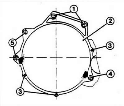
Bolt engine to gearbox
Bolt tightening torques:
- 1 - 80 Nm (М12x55)
- 2 - 10 Nm (М6х8)
- 3 - 10 Nm (М7х12)
- 4 - 80 Nm (М12х64)
- 5 - 60 Nm (M10X140)
The arrows indicate guide bushings for centering the engine and gearbox.
Lower the power unit into the vehicle.
When installing the engine mounts, the notch on the console of the front and rear suspension must enter the clamping pin of the rubber-metal support.
Align the power unit with shaking movements, tighten the screw connections.
Depress the clutch pedal at least five times to the end.
Press the connected control lever approx. 10 mm towards its direction of travel, while it must move freely.
It is necessary to adjust the gas draft, gear shifting, idle speed and, after installing the front of the car, lighting devices.
Tightening torques
Visitor comments