



Diesel engine AMF/BAY/ATD/AXR/ASZ with a working volume of 1.4-/1.9 l
Removal
Remove the top engine cover.
Remove the connecting pipe between the charge air cooler and the intake manifold.
Remove the poly V-belt.
Turn the tension element of the poly V-belt slightly clockwise, remove the T10060 retainer or, respectively, the drill shank/key with an external Allen key from the tension element and unload the tension element.
Remove the upper timing belt cover.
Remove the lower engine compartment cover.
Engine with a working volume of 1.9 l: remove the trim on the right front wheel arch.
Remove the charge air line between the charge air cooler and the turbocharger. Carefully close or plug the inlet openings.
Remove the crankshaft belt pulley.
Remove the lower and middle timing belt covers.
Using a lifting device, slightly lift the engine by the lugs.
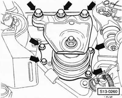
Unscrew the "arrow" mount and remove the engine support.
Caution: Remove the support only when the engine is suspended by the eyes.
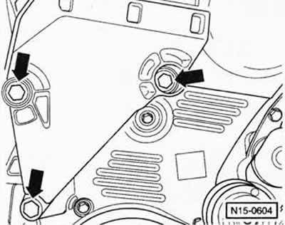
Caution: Loosen the engine bracket mounting bolts "arrows" only when the engine support has been removed.
Loosen the engine bracket fastening to the cylinder block "arrows".
Note: To loosen the upper bolts, lift the engine slightly using a lifting device (approximately 45 mm). To release the lower bolt, lower the engine slightly (approximately 35 mm). To remove the engine bracket, tilt it outward and upward. If necessary, unscrew the pendulum support fastening at the gearbox and move the engine forward a little.
Turning the crankshaft to the position corresponding to TDC for cylinder 1:
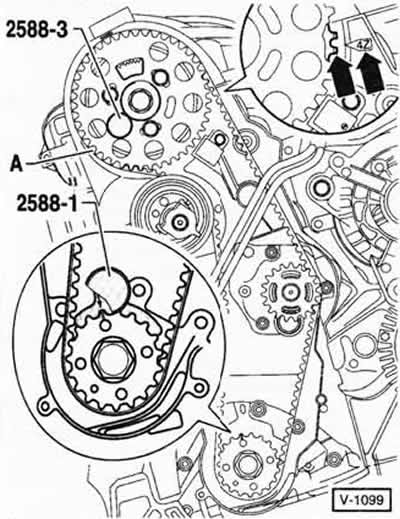
Turn the crankshaft so that the mark on the crankshaft toothed wheel is at the top and the 4Z arrow on the rear protective screen of the toothed belt is opposite the protrusions on the sensor disk located on the hub of the "arrow".
Note: For the 1.4L TDI engine, the TDC marks are in position "A".
The crankshaft can be turned in several ways:
1. Raise the car from the front and side. Engage 5th gear, tighten the handbrake. Turn the raised front wheel by hand. This will also turn the engine crankshaft. An assistant is needed to turn the wheel.
2. Place the car on a level surface. Engage 5th gear and move the car forward or backward.
3. Engage neutral gear, apply handbrake. Turn the crankshaft by the central belt pulley mounting bolt.
Caution: Do not turn the crankshaft using the camshaft timing gear mounting bolt. This will put the timing belt under extreme tension.
Lock the hub of the camshaft gear using the HAZET 2588-3 locking device. To do this, insert the locking device into the cylinder head through the free oblong hole on the left side.
Note: Instead of the HAZET tool, you can also use a regular pin with a diameter of 6 mm.
Lock the crankshaft gear wheel with the special tool HAZET 2588-1. To do this, insert the special tool from the end of the gear wheel into the grooves of the teeth so that the journal of the tool enters the flange of the sealing gasket.
Caution: The marks on the crankshaft gear and the special tool must be aligned with each other. The tool journal must enter the sealing gasket flange. If the special tool is not available, mark the TDC on the sealing gasket flange, see the lower view in Figure V-1099.
Mark the direction of movement of the toothed belt.
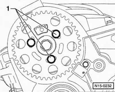
Loosen bolts "1" securing the camshaft gear so that the gear can rotate within the elongated holes.
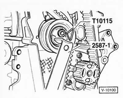
Loosen the tension roller fastening nut. Using the HAZET 2587-1 spanner, turn the tension roller until it can be locked with a suitable locking device, such as the VW-T10115. Then turn the spanner clockwise until it stops and tighten the nut by hand.
Starting from the coolant pump sprocket, remove the timing belt.
Installation
Turn the camshaft gear counterclockwise until it stops.
Place the timing belt on the crankshaft timing gear, tension roller and camshaft timing gear.
Check that the tension roller plate fits into the hole in the rear timing belt guard.
Loosen the fastening nut, turn the tension roller clockwise until it stops and place the toothed belt on the toothed wheel of the coolant pump.
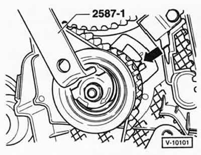
Turn the tension roller counterclockwise with the HAZET 2587-1 spanner and remove the locking pin.
Turn the tension roller with a wrench until the arrow is in the middle of the slot in the carrier plate "arrow".
While holding the tension roller in this position, tighten the fastening nut to a torque of 20 Nm and turn it an additional 45° (⅛ of a turn) in the tightening direction.
Tighten the camshaft gear mounting bolts to a torque of 25 Nm.
Remove the locking tool and the special tool for locking the crankshaft.
Turn the crankshaft in the direction of its rotation by 2 revolutions and set it again to the TDC position for cylinder 1. Shortly before reaching the TDC position during the second revolution, insert the special tool for locking the crankshaft with the journal into the flange of the sealing gasket. If the tool does not fit, turn the crankshaft back by 1/4 revolution and turn it again to the TDC position.
Caution: Do not insert the crankshaft locking tool when turning the crankshaft backwards. If the locking tool is not available, check that the TDC marks made before removal match.
Lock the hub of the camshaft gear using the HAZET 2588-3 locking device.
If the retainer does not fit, proceed as follows:
- Remove the crankshaft locking tool and rotate the crankshaft until the locking pin engages the camshaft timing gear hub.
- Loosen the camshaft gear mounting bolts.
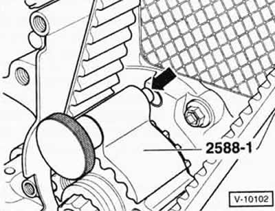
Turn the engine crankshaft slightly against the direction of its rotation so that the journal of the 2588-1 crankshaft locking tool is directly in front of the hole in the flange of the sealing gasket "arrow".
Now turn the crankshaft in the direction of its movement until the journal of the locking tool enters the flange of the sealing gasket.
Tighten the camshaft gear mounting bolts to a torque of 25 Nm.
Remove the crankshaft locking tool and retainer.
Turn the crankshaft in the direction of its rotation by 2 revolutions and set it again to the TDC position for cylinder 1. Shortly before reaching the TDC position during the second revolution, insert the special tool for locking the crankshaft with the journal into the flange of the sealing gasket. If the tool does not fit, turn the crankshaft back by 1/4 revolution and turn it again to the TDC position.
Caution: Do not insert the crankshaft locking tool when turning the crankshaft backwards. If the locking tool is not available, check that the TDC marks made before removal match.
Lock the hub of the camshaft gear using the HAZET 2588-3 locking device.
Remove the crankshaft locking tool and retainer.
Place the engine bracket against the cylinder block and tighten the mounting bolts to a torque of 45 Nm.
Install the engine support with new body mounting bolts and tighten them to 20 Nm. Then tighten the bolts by 90° (¼ turn) in the tightening direction.
Tighten the engine support to the engine bracket to a torque of 30 Nm. Then tighten the bolts by 90° (¼ turn) in the tightening direction.
Install the middle timing belt cover.
Install the lower timing belt cover.
Tighten the crankshaft belt pulley fastening to a torque of 10 Nm. Then turn the bolts in the tightening direction by 90° (¼ turn).
Install the poly V-belt.
Install the upper timing belt cover.
Install the pipe between the charge air cooler and the turbocharger and the pipe between the charge air cooler and the intake manifold.
1.9L engine: Install the right front wheel arch trim.
Install the engine cover.
Visitor comments