
ASY diesel engine with a displacement of 1.9 liters and a power of 47 kW (64 hp)
Removing
Remove the engine top cover.
Remove poly V-belt.
Remove upper toothed belt cover.
Remove vacuum pump for brake booster.
Remove lower engine cover.
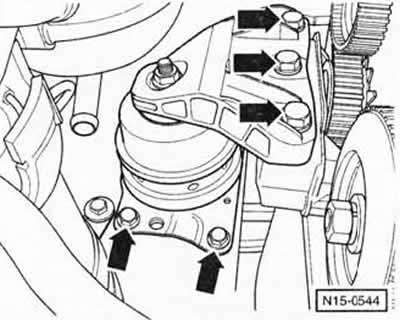
Raise the engine slightly using a jacking tool to relieve the engine support. Remove the engine mount by unscrewing first at the engine bracket and then at the body -arrows-.
Note: The engine mount is attached to the body with 4 bolts, only 2 bolts are visible in the picture.
Remove the middle toothed belt guard.
Remove the engine bracket from the cylinder block.
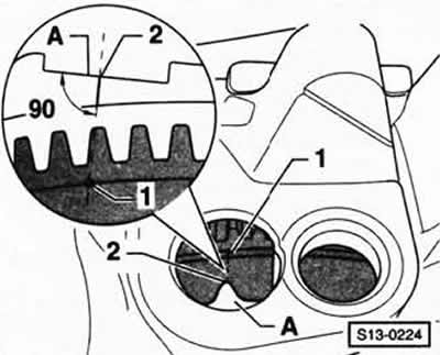
Turn the engine crankshaft to the TDC position for cylinder 1. To do this, turn the crankshaft in the direction of rotation until the mark on the flywheel -1- matches the mark on the gearbox -2-.
Note: To check, look vertically from the side of the milled surface -A-at the gearbox at the mark on the flywheel.

Using the VW-T10098 adjusting ruler, lock the camshaft in the position corresponding to TDC. To do this, screw the centering bolts -1- into the cylinder head by hand as far as they will go.
Note: with the cylinder head cover removed, you can also insert the VW-3418 adjusting ruler into the camshaft groove and use two feeler gauges to align it with the top surface of the cylinder head.
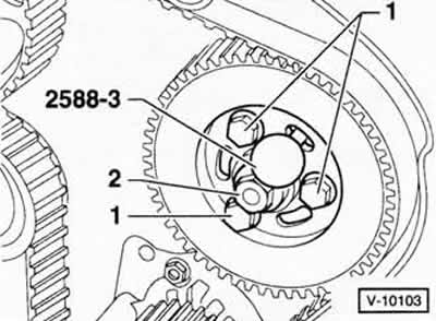
Lock the gear wheel of the injection pump using the VW-3359 or HAZET 2588-3 lock. Alternatively, a 6 mm pin can be used.
Loosen the bolts of the gear wheel of the injection pump, but do not turn it out.
Remove lower toothed belt cover.
Loosen the crankshaft belt pulley.
Mark the direction of travel of the toothed belt.
Loosen the tension pulley nut.
Remove toothed belt.
Installation
Check if the TDC mark on the flywheel matches the alignment mark.
Loosen the camshaft sprocket bolt 1 turn. To do this, remove the cylinder head cover and hold the camshaft by the flats with an open end wrench.
Attention: Do not use the camshaft adjustment ruler as a holder in any case.
Slide the gear off the camshaft using a conventional puller.
Loosen the mounting bolt and remove the gear wheel.
Maintaining the same direction of travel, fit the toothed belt first on the crankshaft sprocket, then on the idler pulley, coolant pump gear and tensioner pulley.
Align the gear wheel of the injection pump in the center of the elongated hole.
Attach the camshaft gear with the toothed belt applied and secure with the fastening bolt. Do not tighten the fastening bolt, the gear wheel on the camshaft must still turn.
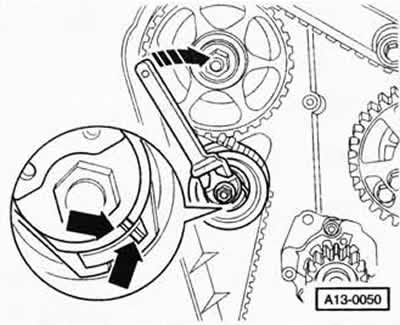
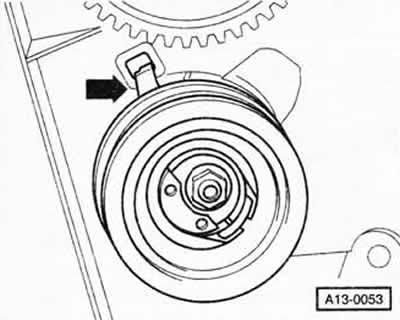
Turn the tensioning roller to the right using a double spanner, eg HAZET 2587. until the notch and projection at the tensioning roller are aligned -arrows-.
Attention: If the tension roller has been overtightened, it must be completely loosened again and then tightened again. Under no circumstances should the tensioner pulley be overtightened by turning it too far.
Tighten the tensioning roller nut to 25 Nm.
Check the installation position of the tensioning roller: the locking plate -arrow- must engage in the recess in the cylinder head, otherwise turn the retainer accordingly.
Again, check the coincidence of the TDC marks on the flywheel.
Tighten the camshaft sprocket central bolt to 45 Nm.
Attention: Hold the camshaft by the flats with an open end wrench. Never use a still installed camshaft shim as a holder.
Tighten the injection pump gear wheel bolts to 25 Nm.
Remove the camshaft shim.
Turn the crankshaft 2 turns and set to the TDC position of the combustion process for cylinder 1. Again check the coincidence of the TDC marks on the flywheel. Check if the camshaft adjusting bar and injection pump sprocket lock are inserted.
Check toothed belt tension. If the notch and the protrusion or, respectively, the notch and the arrow do not match, then tighten the tension roller and tighten the fastening nut to a torque of 25 Nm.
Turn the crankshaft 2 turns and repeat the check operations.
Tighten bolts securing engine bracket to cylinder block to 45 Nm.
Install the engine mount with new mounting bolts.
Tightening torques:
- engine mount to body: 20 Nm + 90° (¼ turn) in the direction of tightening;
- engine support to engine bracket: 30 Nm + 90° (¼ turn) in the direction of tightening.
Install vacuum pump.
Install the lower toothed belt cover.
Tighten the crankshaft pulley to 10 Nm. Then turn the bolts in the tightening direction by 90° (¼ turn).
Note: Mounting is only possible in one position.
Install poly V-belt.
Install lower engine cover.
Install the upper toothed belt cover.
Install the engine top cover.
Check the dynamics of the beginning of the fuel supply (at the service station).
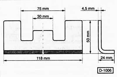
Camshaft adjustment ruler VW-3418:
Visitor comments