



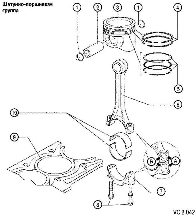
List of parts and components with comments on the installation work (drawing VC2.042):
1. Piston pin retaining ring.
2. Piston pin:
- if installation is difficult, heat the piston to approximately 60°C;
- removal and installation should be done using a mandrel,
3. Piston:
- when reusing the piston, the installation position and cylinder assignment should be marked;
- the arrow on the piston bottom points to the side of the poly V-belt pulley;
- to install the piston into the cylinder, you should use a special piston ring crimper.
4. Compression rings:
- the ring locks must be positioned at an angle of 120* relative to each other;
- remove and install compression rings using piston ring expanders;
- the "TOP" marking must face the piston bottom.
5. Oil scraper rings:
- remove and install the composite oil scraper rings carefully by hand;
- it is impossible to measure the height gap.
6. Connecting rod;
- replace only the entire set;
- mark the cylinder affiliation (at point A);
- installation position: marks (B) point towards the poly V-belt pulley.
7. Connecting rod bearing caps:
- during manufacturing, the connection between the cover and the connecting rod is made by breaking the cover off the connecting rod. Therefore, the cover only fits its connecting rod and only in one position. The fracture surface should be carefully protected from damage.
8. Connecting rod bearing cap fastening screw:
- M7x0.75: 20 Nm + tighten by 1/4 turn (90°);
- M8x1: 30 Nm + tighten by 1/4 turn (90°);
- when installing, the screw should be replaced with a new one;
- lubricate the threads and the seating surface under the screw head;
- to measure the radial clearance in the bearing, the screw should be tightened to the specified tightening torque, but not further turned at an angle.
9. Cylinder block:
- checking the cylinder diameter (see below).
10. Connecting rod bearing shells:
- worn-in bearing shells should be installed in their places;
- the liner is installed in the connecting rod in the center of the seat;
- the radial clearance in the bearing should be measured using a Plasticage measuring gauge.
- Connecting rod bearing clearance:
- for a new engine: 0.020-0.061 mm;
- at maximum permissible wear: 0.091 mm.
- When measuring the radial clearance, it is not permissible to rotate the crankshaft.
Visitor comments