
NOTE: The valve timing can be checked with the engine installed.
Checking procedure
Remove the intake manifold and cylinder head cover. Remove the front noise insulation. Move the crankshaft using the vibration damper mounting bolt in the direction of engine rotation to the TDC cyl. 1 (rice. 2.58).
Camshaft ruler T10068 A must fit into both grooves.
If the camshaft ruler cannot be inserted, rotate the crankshaft again in the direction of engine rotation.
NOTE: If the T10068 A camshaft bar is still not included, turn the crankshaft in the direction of engine rotation about 5mm above TDC cyl. 1 (depends on timing chain tolerances).
Compare the adjustment marks on the phase shifters with the marks on the timing cover.
Marks A and B on the phase shifters must match the notches of the timing cover C (pic. 2.69).
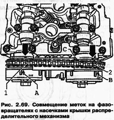
The distance between tooth 1 and tooth 2 of the phase shifter sprockets must be exactly 16 chain rollers.
NOTE: Figure 2.69 shows the valve timing adjustment system with the cover removed.
If the marks do not match, adjust the valve timing.
If the marks match, install the cylinder head cover and intake manifold.
Visitor comments