
Note: During further operations, the ground wire must be disconnected from the battery. Therefore, you must first check whether a radio with coding is installed in the car. If necessary, find out the security code that prevents theft.
Remove the crankcase protection.
Remove the front right and left fender liner.
Bring the radiator frame to the service position.
The engine is removed together with the gearbox down.
Disconnect the battery.
Remove the battery and battery holder frame.
After installing the engine, reinstall all cable ties removed or cut when dismantling it.
Remove the air filter.
Open and close the expansion tank cap to relieve pressure in the cooling system.
Disconnect, disconnect and hang out all electrical wires from the gearbox, alternator and starter.
Remove and disconnect all other existing electrical wires from the engine.
Caution: The fuel line is pressurized to avoid injury and skin contact, wear safety goggles and gloves. Wrap a rag around the connection before disconnecting the hoses. Then release the pressure by gently loosening the connection.
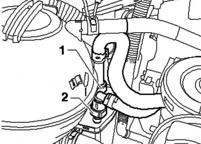
Pic. 2.4. Solenoid valve hose 1 absorber
Disconnect the hose from the activated charcoal canister solenoid valve 1 at the throttle control module (pic. 2.4).
Disconnect the fuel line 1 and line 2 to the solenoid valve 1 of the absorber.
Clog hoses and lines to keep dirt out of the power system.
Follow cleanliness standards.
Disconnect the vacuum and vent hoses from the engine.
Disconnect the connector from the radiator fan.
Remove wiper arms
Remove the plenum box cover/
Removal and installation of the anti-theft engine control unit
Disconnect plug 1 from the heated windshield control unit.
Push the plug locks on the engine control unit to the edges and disconnect both plugs.
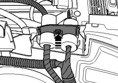
Pic. 2.5. High voltage wire harness bushing lock clip
Unlock the bushing of the high voltage wire harness and remove it by pulling it up (pic. 2.5).
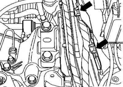
Pic. 2.6. Cable clamps
Open all cable latches (pic. 2.6).
Remove the wiring harness from the engine control unit.
Secure the wiring harness to the engine with a cable tie.
Remove the intake pipe.
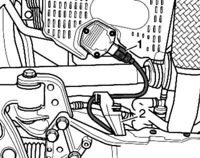
Pic. 2.7. Plug from oil level and temperature sensor
Disconnect plug 1 from the oil level and temperature sensor (pic. 2.7).
Unlock the holder 2 wires to the oil level and temperature sensor from the subframe.

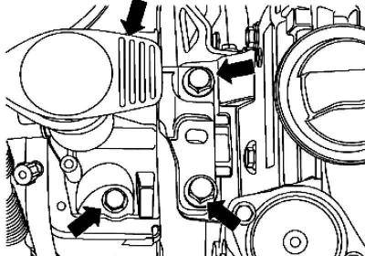
Pic. 2.8. Oscillation mounting bolts
Unscrew the rocker (pic. 2.8).
Unbolt the gearshift drive from the gearbox.
Remove the hydraulic clutch slave cylinder.
Note: Do not press the clutch pedal.
Drain the coolant.
Disconnect the water hoses from the engine using spring clamp pliers VAS 5024A.
Remove poly V-belt.
Remove the air conditioning compressor.
Note: The air conditioning lines cannot be opened.
Attach the air conditioner compressor to the radiator frame.
Check that the hoses are not pinched.
Please observe the additional instructions and installation procedures.
Unscrew the right and left articulated shafts from the gearbox and tie them up.
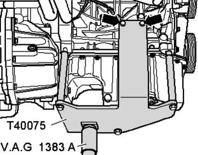
Pic. 2.9. Installing the bracket on the stand
Push the engine clamp onto the engine and gearbox stand VAG 1383 A (pic. 2.9).
Screw the engine clamp with a tightening torque of 20 Nm to the back of the cylinder block.
Note: Use a stepladder to loosen power unit suspension bolts.
Check that all hoses and wires between the engine, body and transmission are disconnected.
Pic. 2.10. Bolts of fastening of the power unit
Unscrew the power unit from the engine mount (pic. 2.10).
Unscrew cable 1 from the transmission cushion.
Unscrew the power unit from the gearbox mount.
Pull the power unit forward as far as possible and slowly lower it down.
Note: Lower the power unit carefully to avoid damage to the body.
Visitor comments