



2. Using a valve spring compressor, compress each spring one at a time to allow the cone retainers (locks) to be removed. After removing the cone retainers, release and remove the valve springs together with the retainers. If it is difficult to remove the retainers, do not bend the springs further, but pry them up with a screwdriver. It is best to use tweezers to remove the retainers.
3. Before removing the valves from the head, it is necessary to mark which cylinder they belong to. To do this, you need to:
- on the valves of the first cylinder, tap - one point at a time,
- the second - two points,
- third - three dots,
- fourth - do not fill in the dots
The dots are punched with a center punch (on the inlet and outlet valves) from the combustion chamber side when the valve rests securely with the entire perimeter of the key against the valve seat. We can stamp similar points on the surface of the combustion chamber so that there is no doubt during installation. The first cylinder is near the timing belt, the fourth cylinder is near the flywheel.
After the valves have been removed, they must be inspected. Very deep scratches on the sealing surface that cannot be rubbed out qualify the valve as requiring replacement. We do the same when the valve is warped or burnt. The end of the stem must be ground to eliminate traces of the valve lever or pusher. Carbon deposits can be removed from the stem with a rotating metal brush.
4. Check the condition of the valve levers. If a certain wear is noticeable on the contact surface of the lever with the cam, then the lever is replaced with a new one. If a dent is noticeable on the working surface of the lever and the valve stem, then the surface of the lever must be ground.
5. Then we check the condition of the valve springs. Broken, damaged or high-mileage springs should be replaced with new ones. If there is any doubt about their condition, you can check the spring bending at a specialized enterprise under a certain pressure.
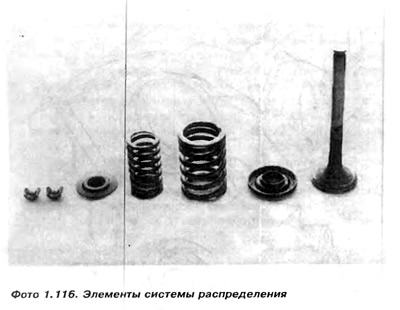
6. Remove the valve guide seals. Then remove the lower valve spring seats (photo 1.116).
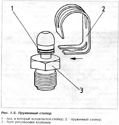
7. Do not unscrew the bolts with ball heads (figure 1.5), unless this is necessary only in the event of damage, as there is a risk of stripping the threads in the head.
8. The carbon deposits must be carefully removed with a comb so as not to damage the sealed surface of the head and valve seats.
It is also necessary to clean the valve plate, paying attention to its sealing surface. A common engine defect caused by a large amount of carbon deposits is self-ignition or difficulty in adjusting the correct ignition advance angle. This is detected when fuel is burned with a knock in the engine, if the ignition advance angle is set according to the adjustment data.
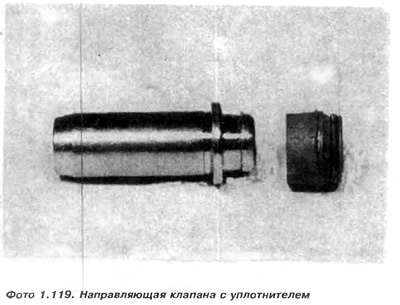
9. Using a scraper, remove all remaining gaskets, then wash the head with kerosene, rinse with water and blow with compressed air.
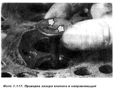
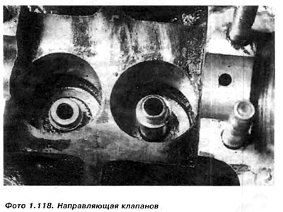
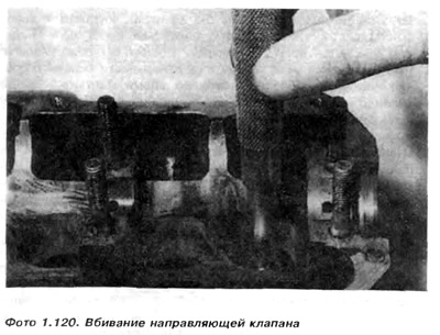
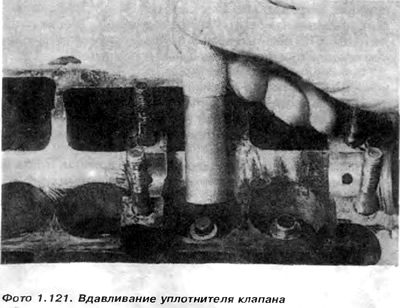
10. Check the valve guide bores for wear and replace if necessary. Check the guide wear by inserting a new valve into the guide and measuring the movement of the valve plate perpendicular to the valve axis, from one extreme position to the other. The valve should be inserted so that the top of the valve stem is in the same plane as the top of the valve guide. The magnitude of this movement should not exceed 1 mm for the inlet valve and 1.3 mm for the outlet valve. For an old valve, these values may be slightly larger. It is necessary to check the guides one by one and. If the measured values (when using a new valve) more data, then the guides need to be replaced. We knock out the used guide with a hammer through a mallet centered on the hole, or we squeeze it out with a press (photo 1.120). The new guide must be pressed in and it is recommended to heat the head to 70°C. We can also put the guide in the freezer. Before knocking out the old guide, it is necessary to measure it, how much it rises above the surface of the head, and also press in the new one. Before pressing in, the hole in the head and the guide must be lubricated with oil. On the press stand, install the head so that the axis of the hole in the head coincides with the axis of the press piston. After pressing in, it is necessary to check the data above the valve travel value.
If a micrometer and bore gauge are available for small holes, the measured installation gap between the valve and the guide should be within 0.03...0.06 mm for new parts and up to 0.15 mm for used parts.
If the internal hole of the corrector is deformed during pressing, it must be drilled out with a calibration drill.
The original can be found at (VWmanual)
The tension between the new guide and the hole in the head should be between 0.06 and 0.10 mm.
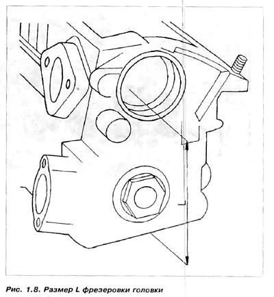
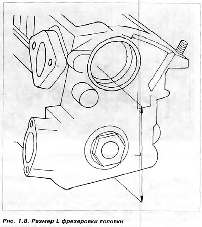
11. Using a ruler and a gap gauge, check whether the surface of the head has been deformed. Pay special attention to the surface between the combustion chambers. A sunken surface in these places entails a weaker gasket pressure. Since the distance between the cylinders is not very large, a weakened gasket pressure increases the possibility of its burnout. If it is possible to insert a 0.1 mm gap gauge between the ruler and the head at any point, then it is necessary to process the surface of the head at a suitably equipped mechanical plant. A common cause of warping of the heads is uneven clamping or squeezing without loosening all the bolts, and later - their complete unscrewing. The value of the dimension L is specified in the technical data. If the layers removed during processing are more than 0.5 mm, it is necessary to mill the valve seats in order to lower the valves deeper by the thickness of the removed layer. This is necessary to prevent the piston from hitting the valve and to avoid warping of the valves. This operation is performed with milling cutters for valve seats, which are aligned with the valve guide axis. The seat must also be milled when there are traces of corrosion and burnt spots are visible, as well as when the valve guides have been replaced. If the corrosion is small, it is enough to remove it with grinding paste.
Attention: Replacement of valve seats must be carried out at a specialized enterprise, since certain conditions must be met during installation.
Before pressing the head, the sockets must be heated to 320° or cooled in liquid nitrogen and the head heated to 100°C.
12. Methods of repairing valve seats: valve seats are repaired by milling and grinding or by grinding and grinding. We will discuss the first method, since grinding requires a very expensive grinding machine. Manual grinding machines do not guarantee the appropriate processing accuracy, because they transmit vibration from the electric motor (in our grinding machines often unadjusted). They are effectively used to remove the hardened surface of the valve seat. After grinding on a stationary grinding machine, no grouting is needed. Milling has the disadvantage that grouting is necessary, because the surface of the seat after processing is slightly wavy. We perform milling of the seat with a set of three cutters with angles of 30°, 90°, 150°. We insert a cutter with an angle of 90° into a chuck with a centering rod, which we insert into the hole of the valve guide and, pressing it to the seat, slowly rotate clockwise. The condition for correct processing is:
a) Making the fitting surface in the form of a flat strip with a width of 1.5 to 2.0 mm (figure 1.8)
b) The angle of this strip should be 90°, and the surface of the strip should be axial with the valve guide hole.
If during milling the strip width exceeds the permissible limit, it is necessary to reduce it using two additional cutters with angles first of 150°, and then of 30°, a cutter with an angle of 90°. The main problem is maintaining coaxiality. Often the holes of the valve guide and the centering rod have a gap that does not allow to avoid errors in coaxiality.
An unaligned socket will require a long period of grouting. You can try to avoid this. After milling the socket (before grouting) it is necessary to insert the corresponding valve, press it slightly with your finger to fit, and turn it several times with your other hand so that it fits properly into the socket. Insert a hose with compressed air into the drive or outlet manifold, but not under very high pressure. Then pour some kerosene onto the pressed valve. The air bubbles that appear will indicate the places where the valve does not fit into the socket. It is the lack of coaxiality that gives such an effect that the valve plate will fit only partially along the perimeter with the socket. It is necessary to re-mill the socket, paying attention to the fact that during rotation, simultaneously push the cutter in the direction of that part of the perimeter from under which the bubbles did not appear. With a certain skill and several attempts, the coaxiality error can be corrected.
Visitor comments