
2. To remove the connecting rods from the pistons, you first need to mark their location relative to the pistons. The sign on the connecting rod is on the side shown by the arrow on the piston bottom. If there are no markings on the connecting rod, we fill a point on the side of the connecting rod to which the arrow on the piston is directed. This will make it easier to install later.
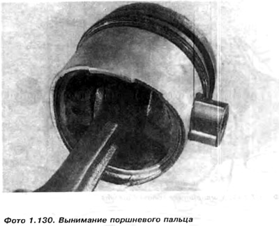
3. Take out the piston ring protectors, then immerse the piston in hot water (about 60°С) and knock out the piston pin.
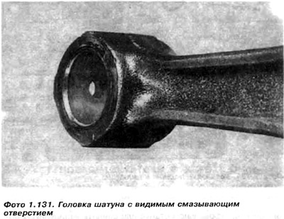
4. If the piston pin extends under its own weight from the horizontally mounted connecting rod, the sleeve and pin must be replaced. We replace the bushing by knocking out the old one, and in its place we press a new one. We make a hole for lubrication in the bushing and turn it to fit the size of the finger, paying attention to the mounting clearance of 0.006 mm. During drilling, the hole in the connecting rod is set vertically. After reaming, the finger should fit snugly into the hole. Poke your finger through the hole several times, and carefully scrape off the sleeve material in the places of the remaining prints. After that, the connecting rod should rotate freely on the pin, but the pin does not move out of the sleeve under its own weight. Before final installation, wipe the surfaces of the sleeve, pin and piston hubs, and then lubricate.
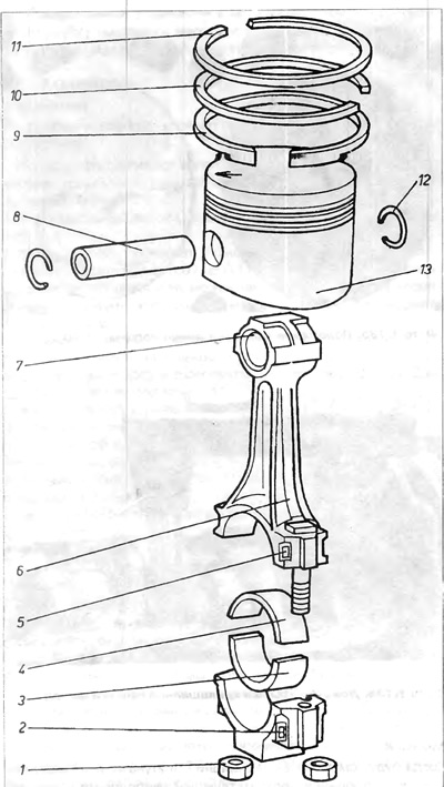
Piston with connecting rod
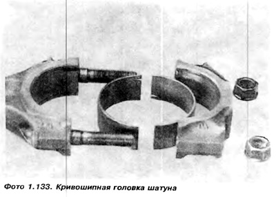
1 - connecting rod bolt nut; 2 - a sign on the cover of the crank head of the connecting rod; 3 - lower half-liner; 4 - upper semi-liner; 5 - a sign on the upper part of the crank head of the connecting rod; 6 - connecting rod rod; 7 - connecting rod head bushing; 8 - piston pin; 9 - oil scraper ring; 10 - sealing ring; 11 - top chrome ring; 12 - piston pin fuse; 13 - piston.
5. Assemble the pistons with the connecting rods in reverse order, paying attention to the correct installation of the piston relative to the connecting rod. It is also important to correctly and securely insert the piston pin guards into the grooves.
Attention: If it is necessary to check whether the axis of the made bushing is parallel to the axis of the hole in the crank head of the connecting rod, it is necessary to return the connecting rods with fitted pins to the factory, where this will be checked on the marking plate and prism using a clock gauge.
If necessary, and it is known from practice that it is usually necessary, the axes should be adjusted. This is called straightening the connecting rods. If the parallelism of the axis is not maintained, after installation the piston will be skewed in the cylinder and will be pressed against one wall. This will cause rapid wear of the cylinder liner on the side of the wall where the piston is pressed, and again there will be a purge between the piston and the cylinder.
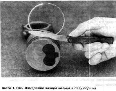
6. Before inserting new rings, it is necessary to place each of them in the cylinder bore, about 15.0 mm from the bottom edge and check whether the clearance on the piston ring locks is the same as in "Technical Data". If the gap is very large, the ring to be checked must be replaced with a new one. If the gap is very small, it is necessary to grind the ends of the ring on a special grinding machine or cut it with a linen file. With a very small gap, the ring cannot expand and may burst.
7. We put the rings on the piston using special tongs or sticking them into three thin probe plates, for example, 0.1 mm, which help to avoid the rest of the grooves on the piston.
8. When putting the rings, it is necessary to check whether the TOP designations on the rings are facing the piston bottom, and set the ring locks to 120°. We check with a feeler gauge whether the values of the gaps of the rings in the grooves of the pistons correspond to those indicated in "Technical Data".
Attention: Before installing pistons with connecting rods in the cylinder, they can be mounted on suitable lubricated (covered with oil) trunnions of the crankshaft. It is known from practice that it is easier to check the fit before mounting than, as suggested by the manufacturer, after mounting the shaft in the motor. The connecting rods should rotate fairly easily and without burrs. If any rotates heavily, it is necessary to remove it and measure both the trunnion and the hole in the crank head of the connecting rod. Shaft trunnion dimensions are given in "Technical Data". If the size is incorrect, the trunnion must be sanded again. Do not scrape connecting rod bearings. When measuring the hole in the liner, the foot cover must be tightened by the same torque as during installation (cm "Technical data". If the hole with the liner shows ovalization, take out the liner and, after twisting, measure the hole without the liner. In case of ovalization of the hole in the crank head of the connecting rod, it is necessary to replace it with a new one. Remember that the connecting rods must be placed on the trunnions according to the previously entered designation.
Visitor comments