
A) We place the head with the combustion chambers up on the rack in the workshop and put wooden blocks on each side.
b) We attach copper or brass nuts to the valve plate from the side of the combustion chamber, with which we will rotate the valve during grouting
V) We put a soft spring under the valve plate, for example. from the fuel pump. She will tear off the valve from the socket during grouting,
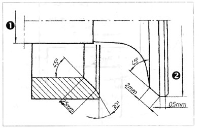
Fig 1.9. Valve and head seat dimensions
1 - intake - 7.97, exhaust - 7.95; 2 - intake - 34 mm, exhaust - 31 mm
Attention: Separation of the valve from the surface to be rubbed after a certain time is necessary for a constant supply of paste to the fitted socket.
G) We apply a little carborundum coarse-grained paste on the surface of the nest and, using a grinding machine, finished, for example, with a spanner, rub both elements one to the other in half turns, after a certain time raising the valve to distribute the erasing paste. After obtaining a matte surface on the valve seat and on the valve, it is necessary to wipe off the paste and repeat the same operation with fine-grained carborundum paste. Grinding is completed after obtaining a perfectly smooth, light gray matte ring on the valve and seat.
To check the tightness of a worn valve, it is necessary to mount it in the head along with springs and fuses. If it is a drive valve, kerosene must be poured into the drive port of that cylinder. Install the head vertically with the drive manifold up and wait 10 minutes. If after this no kerosene seeps into the combustion chamber, the valve can be considered tight.
d) After grouting is completed, it is necessary to thoroughly rinse and blow out the combustion chamber of the valve seats, guide holes, manifolds - inlet and outlet - from carbon deposits and erasing paste.
1. Lubricate the surface of the fitted valve seat, valve stem, and guide bore before mounting.
2. If possible, compare the length of the valve springs with new ones and replace the entire set if one is shorter.
3. If the engine is in a car, it is necessary to clean the bottoms of the pistons and the upper faces of the cylinder bushings. Pay attention that the deposit has not got between the piston and the cylinder. Set two pistons to TDC. protect other cylinders. Carbon particles must not be allowed to get into the cylinders or the oil and water channels of the R block. this will make it easier for contaminants to get between the piston and cylinder.
4. In order to localize a possible crack in the head, it is necessary to drain the coolant before dismantling and drink water with the addition of ink into the system. Warm up the engine, as some leaks appear only when the head is hot. After removing the engine, traces of ink will remain in the places of cracks.
If this could not be done, it is necessary to plug all the water holes with wooden plugs, except for one into which compressed air is supplied. By placing the head in a bath of hot water, you can see air bubbles in places where the connection is leaking. We do the same with oil channels.
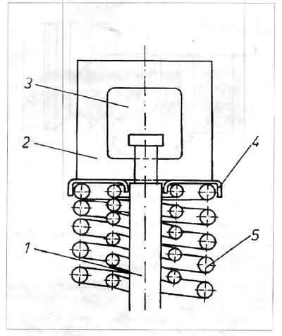
Fig 1.10. Taper Ring Installer
1 - valve stem; 2 - device (adaptation); 3 - window for installing fuses; 4 - upper cup; 5 - external valve spring
Visitor comments