



1. Remove the cylinder head.
2. Unscrew and remove the oil pump.
3. Unscrew and remove the oil pump container with the gasket.
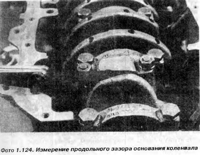
4. Using a feeler gauge, check whether the longitudinal clearance of the connecting rod head on each crank journal corresponds to the dimensions specified in the "Technical Data" (photo 1.124). If not, it is necessary to check which element is responsible for the increased clearance and replace it if necessary. It may happen that the connecting rod is thinner than necessary, or, which happens more often, the crankshaft journal width has increased due to inattentive grinding.
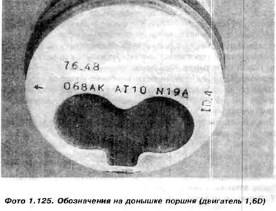
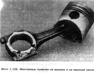
5. Before removing the head cover of the first connecting rod, it is necessary to turn the crankshaft so that the piston is at BDC (bottom dead center). Pay attention to the markings on the connecting rod head cover, on the connecting rod rod, and also on the piston crown. The arrow on the piston crown points towards the timing belt (photo 1.125). The marks on the connecting rod and on the connecting rod head cover must also be directed towards the timing belt (photo 1.126). This is intended to clearly identify the position of the piston and connecting rod with the cap relative to a constant reference point. If these markings do not correspond, one to four points can be punched. Readable and unambiguous markings are very important, especially during subsequent assembly. The cap cannot be turned relative to the connecting rod by 180°, nor can it be screwed to another rod.
The order of the cylinders is as follows: the first is located near the timing belt, the fourth is near the flywheel.
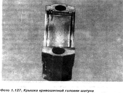
6. Unscrew the nuts and remove the connecting rod crank cap together with the bearing shell. Pay attention to the bearing shell tongue that fits into the socket in the cap. It serves to lock the bearing shell before rotation. It should also be inserted into the socket during mounting (photo 1.127).
7. Use the hammer handle to knock the piston and connecting rod out of the cylinder.
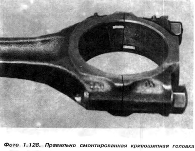
8. Connect the cover to its connecting rod, paying attention to its position relative to the connecting rod rod. It should be the same as in the engine. To do this, use the dots previously stamped on the cover and on the upper part of the crank head before disconnecting. The universal principle is to connect the cover as in photo 1.128, so that the locks on both parts of the connecting rod crank head are on the same side.
9. Repeat the steps described in paragraphs 9.5-9.8 for the pistons and connecting rods first for cylinder 4, and later, after turning the shaft, for cylinders 2 and 3.
10. The manufacturer recommends replacing the connecting rod bolts with new ones every time.
Visitor comments