
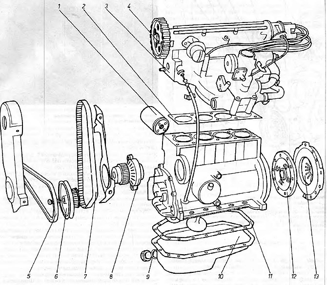
Engine 1.1 and 1.3
1 - oil filter; 2 - head gasket; 3 - engine head; 4 - distribution gear; 5 - V-belt; 6 - pulley; 7 - toothed belt; 8 - water pump; 9 - oil drain plug gasket; 10 - oil sump; 11 - oil crankcase gasket; 12 - clutch disc; 13 - clutch booster.
1. Disconnect the battery cable with a minus sign.
2. Remove the engine hood, and place it in a safe place so as not to scratch it.
3. Drain the engine coolant and remove the radiator, along with the cooling fan kit.
4. Remove the air filter cover.
5. Loosen the clamp and disconnect the upper elastic wire from the thermostat housing.
6. Place a suitable container under the engine, then unscrew the drain plug from the oil sump and drain the oil. After finishing, clean the drain plug and gasket and screw it back on.
7. Disconnect the flexible fuel pipes from the fuel pump, as well as the return pipe from the carburetor (returnable) excess fuel is returned from the carburetor to the fuel tank. Clamp or plug the flexible pipes to prevent fuel from leaking out of the tank.
8. Loosen the clamp and disconnect the lower coolant hose at the rear of the engine.
9. Disconnect the throttle cable and the cable that controls the valve of the starting equipment in the carburetor.
10. Disconnect the heater wires from the thermostat housing and wires 12 (see fig. 2.4).
11. Disconnect the flexible pipes from the following equipment, marking each pipe during disconnection to avoid errors during reconnection:
- A) Oil pressure sensor at the end of the cylinder head (from the carburetor side)
- b) Mixture heater in drive manifold
- V) Radiator fan thermal switch
- G) Ignition apparatus (low and high voltage wires)
- d) Starter
- e) temperature sensor (thermostat housing)
- and) Idle solenoid valve in carburetor
- h) Ground wire for gearbox
12. Remove the bundle of wires attached to the lower elastic wire from the bar and hang it up.
13. Loosen the clamps and disconnect the rarefied air pipes from the ignition apparatus and drive manifold (if necessary)
14. Disconnect the clutch cable.
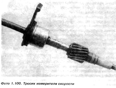
15. Disconnect the speed meter cable from the gearbox and hang it on its side.
17. Tighten the handbrake, then raise the front of the car and install on supports.
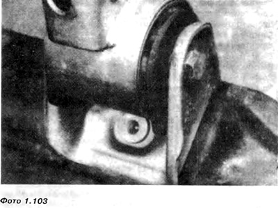
18. Unscrew the bolt from the detachment of the longitudinal rod of the gear lever and transfer the connection to the rods (photo 1.101). The bolt threads are coated with a liquid blocking agent and it may be necessary to heat the joint with a blowtorch. Then remember to take precautions.
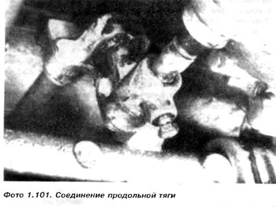
19. It is necessary to pay attention to the position of the connector in relation to the rod or mark it (which will make installation easier) and then pull out the connecting longitudinal rod. The correct position of the connector relative to the rod will ensure the correct engagement of the gears.
20. Loosen the exhaust pipe bracket bolt to disengage it from the down pipe and clutch and starter housing.
21. Disconnect the reverse light switch wiring.
22. Disconnect drive shafts from drive flanges (section 7), tie them with wire and protect the hinge from contamination by wrapping it with foil.
23. Using a winch or a hoist with a lifting capacity of min 250, hang the engine on the brackets provided for this. bolted to the head on the carburetor side.
24. Unscrew the top three bolts of the engine mount bracket (below the carburetor).
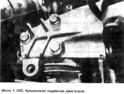
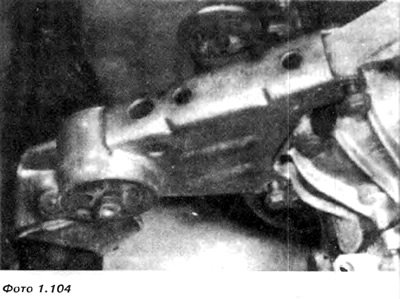
25. Loosen and remove the engine mount bracket bolt, and then. Remove the bolts securing the bracket to the engine. Extend bracket (photo 1.104).
27. Removing the engine and gearbox as a set requires the help of a second person who will not allow damage to the elements | surrounding the engine during extraction.
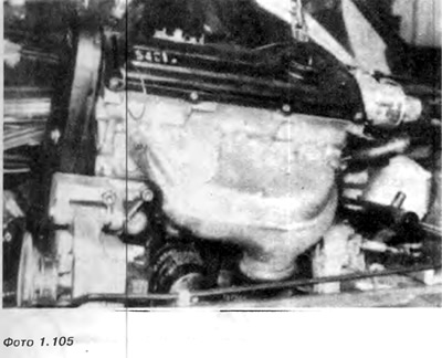
28 Remove the complete engine and gearbox from the engine chamber (photo 1.105), rotating it if necessary so. so as not to hurt other elements. During the removal of the engine, it is necessary to check whether all electrical wires, cables and flexible pipes are disconnected.
29. Pull back the car
30. Place the knot on the frame or on the boards lying on the floor.
Visitor comments