
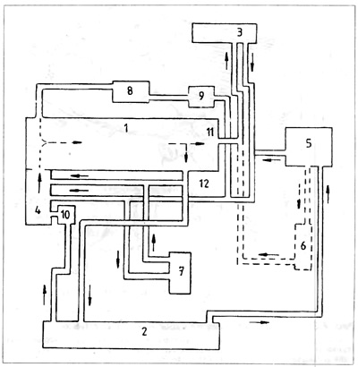
Pic. 2.1. Cooling System Diagram
1 - engine, 2 - radiator; 3 - stove; 4 - water pump: 5 - surge tank; 6 - automatic transmission oil cooler; 7 - engine oil cooler; 8 - turbocharger; 9 - coolant pump; 10 - thermostat; 11 - outlet fitting; 12 - outlet fitting
The cooling system in the Golf and Jetta is a pressurized cooling system and consists of:
- Radiator 2, placed in front of the car with an electric fan.
- Water pump 4 screwed to the engine housing 1.
- Coolant pump 9 Turbocharger 8 (if available).
- Thermostat 10, which turns off the radiator from the circulation of the coolant.
- Furnace 3, heating the interior of the car.
- Engine oil cooler 7.
- Oil cooler automatic transmission 6 (if available).
- surge tank 5.
- Outlet fitting 11, screwed to the head above the flywheel. Outlet fitting 12, screwed to the head from the side of the spark plugs or injectors
- Radiator fan thermal switch 14 (pic 2.3). Coolant temperature sensor.
- Elastic and metal connecting pipes. The radiator has a construction made of aluminum. This is a set of tubes connected by radiator plates that facilitate the transfer of heat to the air passing through the radiator. Radiator plates strengthen the design of the radiator and increase its usable area.

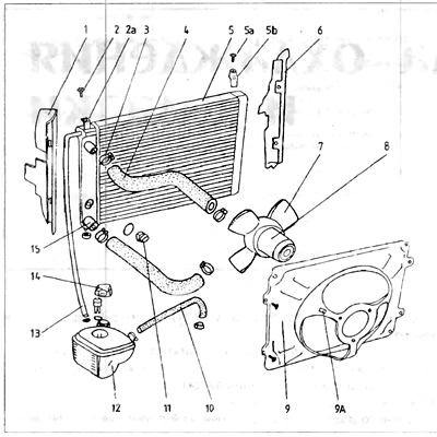
Pic. 2.3. Cooling system - engine 1.6 and 1.8 l
1 - left cover; 2 - bolt securing the radiator; 2a - permanent fixing bracket; 3 - radiator, For - fixing bolt; Zb - removable bracket; 4 - clamping belt; 5 - branch pipe of the head / radiator; 6 - right cover; 7 - branch pipe of the surge tank / radiator; 8 - the lower branch pipe of the radiator / water pump. 9 - fan cover; 9a - fastening wires supplying the radiator; 10 - fan motor; 11 - fan blades; 12 - branch pipe of the surge tank / branch pipe of the stove; 13 - surge tank; 14 - radiator thermal switch; 15 - sealing ring (o-ring)
The fan is mounted on the radiator with a casing 9 made of tin. The fan consists of a plastic propeller 7 and an electric motor 8 driving it (pic. 2.2). It forces air through the radiator, especially when the car is moving at low speed, such as down a city street. The signal that turns on the radiator fan is the coolant temperature.
Pic. 2.2. Cooling system - engines 1.1 and 1.3 l
1 - left cover; 2 - bolt securing the radiator; 2a - permanent fixing bracket; 3 - clamping belt; 4 - branch pipe of the head / radiator; 5 - radiator; 5a - fixing bolt; 5b - removable bracket, 6 - right cover. 7 fan blades 8 - fan motor, 9 - fan cover; 9a - fastening of wires supplying the fan; 10 - branch pipe of the surge tank / branch pipe of the stove; 11 - radiator thermal switch; 12 - surge tank. 13 - branch pipe of the surge tank / radiator; 14 - cork; 15 - outlet fitting
If the temperature of the coolant rises above 93-98°C, the thermal switch 11 will turn on the fan. If the coolant temperature drops to 88-93°C, the same thermal switch will turn off the fan. The coolant temperature sensor is connected by an electrical wire to the temperature gauge on the instrument panel. It informs the driver about the current coolant temperature.
Water pump 4 (fig 2.1) It has a standard design and is driven by a crankshaft. In engines 1.1 and 1.3, the water pump is driven by a distribution belt, and in engines 1 6 and 1.8 - by a V-belt. The water pump is used to force the circulation of water in the cooling system Forced circulation cooling allows large amounts of heat to be dissipated. An engine with such a system can work with a higher load and have a high compression ratio. In engines equipped with a turbocharger 8, an electric coolant pump 9 is additionally mounted in the system. It forces the coolant to pass through the turbocharger when the temperature of the coolant in the turbocharger exceeds 105°C This can happen, for example, after turning off a hot engine when the main pump stops working. The passage of coolant through the radiator is controlled by a thermostat, the location of which may vary depending on the type of engine. In engines 1.1 and 1.3 l Fig. 2.4) thermostat 5 is housed in housing 3 bolted to the back of the engine head below the ignition mechanism. In engines 1.6 and 1.8 (pic. 2.5; thermostat 3 is located at the base of the water pump housing, fixed below the front of the engine (from the side of the distribution belt shield).
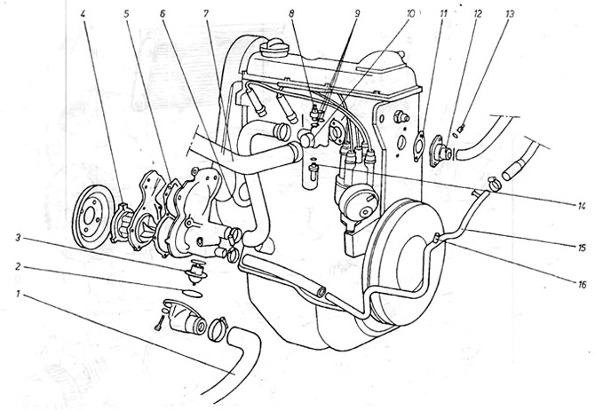
Pic. 2.4. Cooling system - engines 1.1 and 1.3 l
1 - thermal switch 2 - gasket; 3 - thermostat housing; 4 - gasket; 5 - thermostat; 6 - cover gasket; 7 - thermostat cover; 8 - radiator; 9 - water pump gasket; 10 - water pump; 11 - manifold outlet fitting; 12 - metal tube; 13 - elastic pipe; 14 branch pipe of the thermostat housing / head; A - entrance to the metal tube from the lower radiator pipe; B - entrance to the metal tube from the stove; C - exit from the thermostat housing; D - outlet from the thermostat to the radiator; E - entrance to the metal tube from the drive manifold; F - outlet from the thermostat housing to the drive manifold
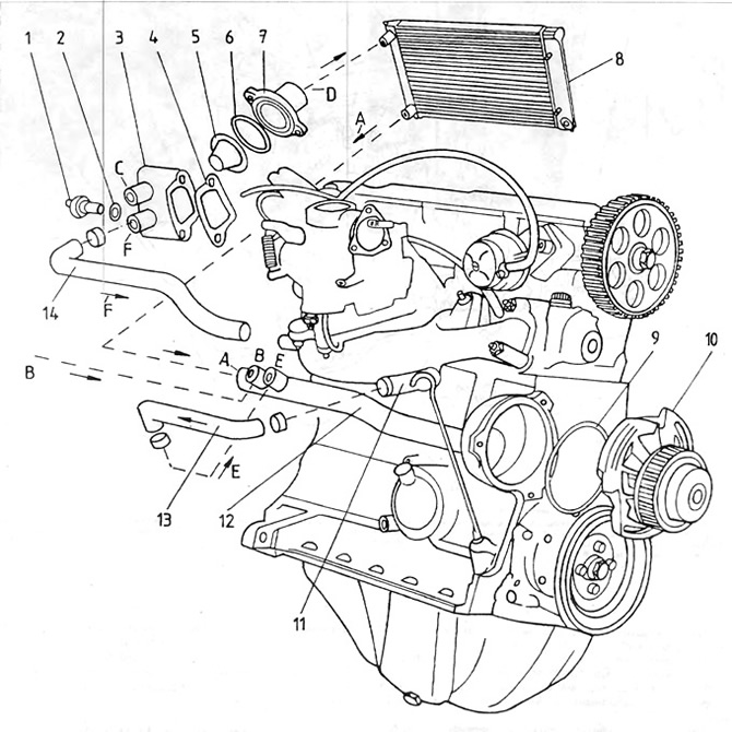
Pic. 2.5. Cooling system - 1.6 and 1.8 liter engines
1 - radiator / water pump pipe; 2 - thermostat cover washer; 3 - thermostat; 4 - front cover with blades; 5 - gasket; 6 - input channel to the engine housing; 7 - branch pipe of the head / radiator; 8 - thermal switch; 9 - gasket; 10 - outlet fitting to the radiator; 11 - gasket: 12 - outlet fitting from the head; 13 - temperature sensor; 14 - thermal switch; 15 - return pipe from the stove; 16 - the place of connection of the branch pipe from the surge tank
The stove is located inside the passenger compartment, which heats. To adjust the amount of fluid circulation through the stove, the so-called stove valve is used, which is controlled from inside the car (see section "Body"). A fuel injected or turbocharged engine has an oil cooler 7 (pic. 2.1), which is cooled by water from the cooling system.
The oil cooler is located between the oil filter and the oil filter bracket and is bolted to the engine housing.
Surge tank 5 (pic. 2.1) placed in the engine compartment. In some models, it is equipped with a coolant level sensor. The equalization tank is connected by a rubber hose to the return pipe (stove-water pump).
In cars with automatic transmission and turbocharging, an oil cooler of gears 6 is mounted (pic. 2.1). The idea is. so that at developed high powers, the stickiness of the oil does not fall below the limit, after which the correct operation of the gears decreases.
Visitor comments