
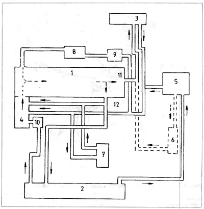
Pic. 2.1. Cooling System Diagram
1 - engine, 2 - radiator; 3 - stove; 4 - water pump: 5 - surge tank; 6 - automatic transmission oil cooler; 7 - engine oil cooler; 8 - turbocharger; 9 - coolant pump; 10 - thermostat; 11 - outlet fitting; 12 - outlet fitting
Two outlet fittings are screwed to the head. Through fitting 11 screwed over the flywheel, hot coolant enters the stove (stove valve open). Liquid flows out of the stove through pipe 15 (pic. 2.5) to the water pump 4.
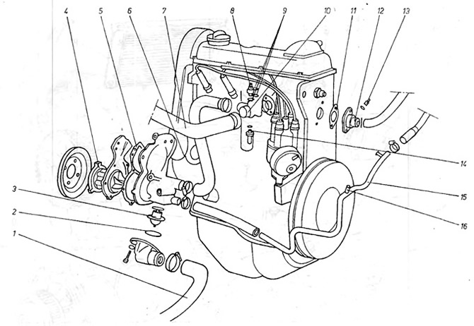
Pic. 2.5. Cooling system - 1.6 and 1.8 liter engines
1 - radiator / water pump pipe; 2 - thermostat cover washer; 3 - thermostat; 4 - front cover with blades; 5 - gasket; 6 - input channel to the engine housing; 7 - branch pipe of the head / radiator; 8 - thermal switch; 9 - gasket; 10 - outlet fitting to the radiator; 11 - gasket: 12 - outlet fitting from the head; 13 - temperature sensor; 14 - thermal switch; 15 - return pipe from the stove; 16 - the place of connection of the branch pipe from the surge tank
Through fitting 12, screwed to the head on the side of the spark plugs, the coolant flows directly into the water pump (when the stove valve is closed).
In the cooling system, two circles of fluid circulation are distinguished - a small and a large circle. In a small circle, the liquid circulates as follows: water pump-cat al of the body-channels of the head-fitting 12-water pump. If the stove valve is open, the small circle is enlarged by the stove circuit connected in parallel.
The large circle turns on when the coolant is heated to a temperature of 37-102°C. Then the thermostat opens and the water begins to circulate as follows: water pump - channels of the body and head - fitting on the side of the spark plugs - upper rubber pipe - radiator - lower rubber pipe - thermostat - water pump (see figure 2.1).
The air passing through the radiator picks up the heat of the coolant, and the cooled liquid flows down to the bottom of the radiator. If necessary, cooling is enhanced by an electric fan.
When the cooled liquid drains to the bottom of the radiator, it then flows into the water pump, and a new cooling cycle begins.
The action of the electric fan is controlled by a thermal switch 14 (pic. 2.3), located on the left side of the radiator.
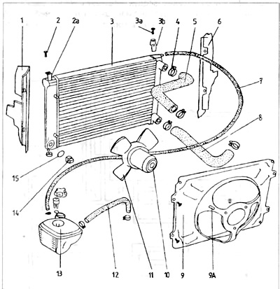
Pic. 2.3. Cooling system - engine 1.6 and 1.8 l
1 - left cover; 2 - bolt securing the radiator; 2a - permanent fixing bracket; 3 - radiator, For - fixing bolt; Zb - removable bracket; 4 - clamping belt; 5 - branch pipe of the head / radiator; 6 - right cover; 7 - branch pipe of the surge tank / radiator; 8 - the lower branch pipe of the radiator / water pump. 9 - fan cover; 9a - fastening wires supplying the radiator; 10 - fan motor; 11 - fan blades; 12 - branch pipe of the surge tank / branch pipe of the stove; 13 - surge tank; 14 - radiator thermal switch; 15 - sealing ring (o-ring)
In carbureted engines, the drive manifold is heated to increase fuel evaporation.
Branch pipe 14 (pic 2.4) allows coolant to flow from port F to the drive manifold.
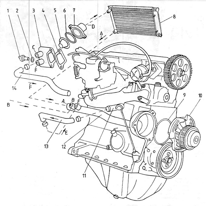
Pic. 2.4. Cooling system - engines 1.1 and 1.3 l
1 - thermal switch 2 - gasket; 3 - thermostat housing; 4 - gasket; 5 - thermostat; 6 - cover gasket; 7 - thermostat cover; 8 - radiator; 9 - water pump gasket; 10 - water pump; 11 - manifold outlet fitting; 12 - metal tube; 13 - elastic pipe; 14 branch pipe of the thermostat housing / head; A - entrance to the metal tube from the lower radiator pipe; B - entrance to the metal tube from the stove; C - exit from the thermostat housing; D - outlet from the thermostat to the radiator; E - entrance to the metal tube from the drive manifold; F - outlet from the thermostat housing to the drive manifold
After the heat is released in it, the coolant flows through the pipe 13 into the fitting E and then through the pipe 12 into the water pump 10.
In diesel engines 1.6, the drive manifold is not heated. to increase the filling of the cylinders.
Hot air contains less oxygen per unit volume than cold air. The less oxygen, the less fuel burns, and the less power is developed by the engine.
Visitor comments