



Contents: Extraction ↓ Examination ↓
Extraction
Thermostat 5 is located in the body of the outlet fitting 3 (Fig. 2.2), screwed to the head above the flywheel.
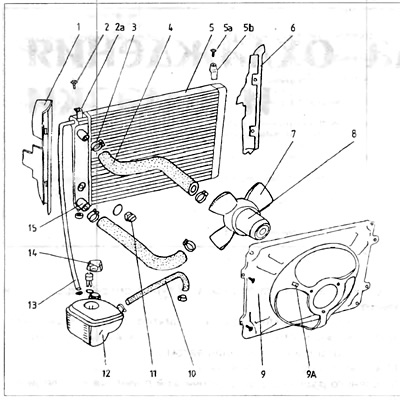
Figure 2.2. Cooling system - 1.1 and 1.3 l engines
1 - left cover; 2 - bolt securing the radiator; 2a - permanent mounting bracket; 3 - pressure belt; 4 - head/radiator pipe; 5 - radiator; 5a - fastening bolt; 5b - removable bracket, 6 - right cover. 7 fan blades 8 - fan motor, 9 - fan cover; 9a - fastening the wires supplying the fan; 10 - expansion tank pipe/heater pipe; 11 - radiator thermal switch; 12 - expansion tank. 13 - expansion tank/radiator pipe; 14 - cork; 15 - outlet fitting.
To extract it, you first need to:
1. Drain the liquid from the cooling system.
2. Loosen the bolts and remove the thermostat cover 7. Set the cover with the upper hose aside.
3. Remove the o-ring 6.
4. Remove the thermostat from the housing.
Examination
5. To check if the thermostat is fit for use, measure its initial length. Hang it in a container with water so that it is completely immersed in water. Gradually heat the water and record the temperature at which the thermostat begins to open.
This temperature should be 88°C. Having heated the water to a temperature of 102°C, at which the thermostat should open completely, check whether the thermostat has lengthened by 7 mm in relation to the length before heating. Then check its length again after cooling - it should be the same as before heating.
6. Replace the thermostat with a new one if it does not work properly.
7. Clean the thermostat housing and the sealed surfaces of the housing and cover.
Installation
Installation is performed in the reverse order of removal. It is necessary to replace the o-ring with a new one and tighten the cover bolts with a torque of 10 Nm. The air outlet hole must be facing upwards. Fill the cooling system with liquid.
Visitor comments