



Contents: Mounting the engine on a mounting…↓ Work execution procedure ↓ Installation instructions ↓ Tightening torques ↓
Note: For further operations, the ground wire must be disconnected from the battery.
Note: The engine is removed together with the gearbox downwards.
Note: Leave the key in the ignition to prevent the steering wheel from locking.
Note: Before starting to dismantle the power unit, it is recommended to remove the front wheels. This will allow the car to be lowered on the lift, leaving a few centimeters between the brake disc housings and the floor. This will ensure optimal accessibility to all components in the engine compartment during work.
Note: After installing the engine, all cable ties that were removed or cut during engine dismantling must be reinstalled.
Note: To avoid damage to removed parts, a container for removed parts should be used.
Note: Some components in this vehicle cannot be removed or are difficult to remove without removing the engine. Therefore, before removing the engine, it is necessary to identify all faulty parts and replace them after removing the engine.
Caution: When performing all installation work, particularly in the engine compartment, due to the tight layout, please pay attention to the following.
Attention: Highways of all types (for example fuel, hydraulic, activated carbon canister, cooling systems, air conditioning circuits, brake lines, vacuum hoses), and also the electrical wires must be laid as they were originally laid.
Caution: Provide clearance for all moving and hot components.
Before removal, interrogate the fault memory of all control units.
Disconnect the ground wire from the battery with the ignition off.
Remove the engine cover.
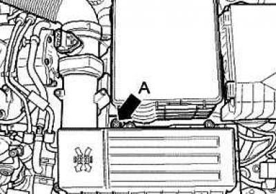
Fig. 2.253. Air filter housing mounting screw
Loosen screw A, pull air filter housing up from mount (fig. 2.253).
Remove the air filter housing together with the air flow meter and connecting pipe.
Disconnect any necessary vacuum hoses or, if applicable, the plug connection at the solenoid valve block.
Remove the battery and the battery holder frame.
Remove the wiper arms.
Remove the water drainage box casing.
Cars without anti-theft alarms
Unlock the connecting plugs from the engine control unit and disconnect them.
Cars with anti-theft alarms
Unlock the connecting plugs from the engine control unit and disconnect them.
Continuation of installation operations for all vehicles
Remove the wiring harness/engine control module grommet.
Open the cable management clamps.
Remove the engine wire harness from the wiring harness on the side member and place it on the engine.
Remove the fuel supply line, fuel return line and coolant hose.
Caution: Fuel and fuel lines may be hot.
Caution: Also, the fuel system is under pressure. Before opening the system, place a rag around the connections and relieve the pressure by slowly loosening these connections
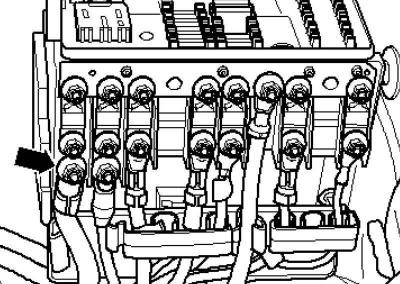
Fig. 2.85. Fastening the generator cable to the fuse box
Remove the cable from the vehicle's central distribution unit (Fig. 2.85).
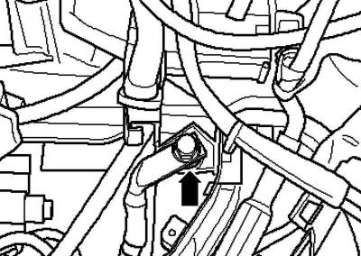
Fig. 2.86. Fastening the ground cable
Unscrew the ground cable from the side member (Fig. 2.86).
Set aside the cables.
Remove the terminals, disconnect and release all remaining existing electrical wires from the engine/transmission.
Disconnect all connecting, vacuum and intake hoses from the engine.
Front wheel drive cars
Disconnect the gear shift drive from the transmission.
All-wheel drive vehicles
Remove the gear shift actuator from the transmission.
Continuation of installation operations for all vehicles
Remove the clutch hydraulic slave cylinder.
Remove the sound insulation.
Disconnect the plug on the oil level and temperature sensor.
Disconnect the wire harness retainer from the oil level and temperature sensor on the subframe.
Drain the coolant.
Bring the radiator frame to the service position.
Remove the exhaust pipes completely from the auxiliary heater.
Remove the cooling system hoses from the auxiliary heater.
Disconnect all remaining cooling system hoses from the engine.
Remove the right drive shaft and unscrew the left drive shaft from the gearbox.
All-wheel drive vehicles
Remove the front propeller shaft pipe.
Cars with particulate filter
Loosen the front exhaust pipe/front muffler connecting clamp.
Remove the subframe together with the steering gear.
Note: The engine is removed with the diesel particulate filter installed downwards.
Cars without a particulate filter
Unscrew the exhaust pipe from the turbocharger, unscrew the double clamp and remove the exhaust pipe.
Continuation of installation operations for all vehicles
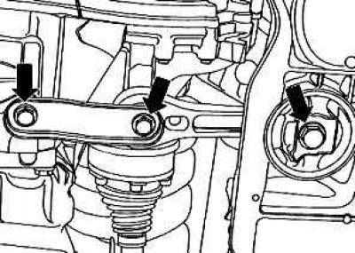
Fig. 2.254. Swing support mounting bolts
Unscrew the rocker support (fig. 2.254).
To remove and install the engine without depressurizing the air conditioning system, remove the poly V-belt.
Unscrew the air conditioning compressor from the bracket.
Secure the air conditioning compressor to the radiator frame so that the air conditioning system circuit pipes/hoses are not stretched.
Note: To avoid damage to the condenser and the air conditioning system circuit lines and hoses, ensure that the lines and hoses are routed without tension, kinks or bends.
Screw the engine retainer with a fastening nut and bolt M10x25/8.8 with a tightening torque of approximately 40 Nm to the cylinder block.
Install the engine mount into the engine and transmission stand.
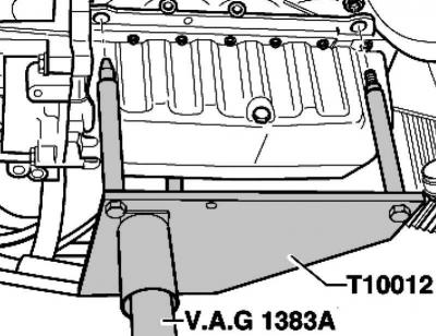
Fig. 2.95. Installing the rack
Raise the engine and gearbox slightly using an engine and gearbox stand (Fig. 2.95).
Note: Use a step ladder to remove the mounting bolts.
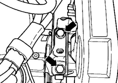
Fig. 2.96. Fastening the upper engine mount bracket
Unscrew the cushions on the engine side at the top of the engine support (Fig. 2.96).
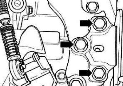
Fig. 2.255. Engine mount bolts
Unbolt the transmission side mounts from the transmission bracket (fig. 2.255).
Lower the engine and gearbox down.
Note: Lower the engine and gearbox carefully to avoid damage to the body.
Mounting the engine on a mounting stand
To perform installation work, the engine must be secured using an engine and gearbox clamp on the mounting stand clamp or on an engine and gearbox clamp.
Work execution procedure
Separate the gearbox.
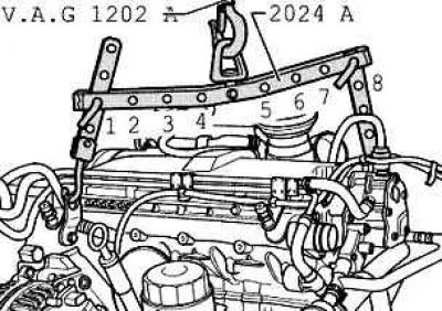
Fig. 2.256. Engine suspension
Hang the hanger properly and lift the engine with a crane or crane from the engine and gearbox stand (fig. 2.256).
From the belt pulley side, 2 guide holes are in position 1.
From the flywheel side, 4-hole guide in position 8.
Caution: Use safety pins on hooks and locking pins.
Note: Holes 1-4 of the carrier bar point towards the belt pulleys.
The number of holes in the planks is counted from the hook.
Secure the engine with the engine and transmission clamp to the mounting stand jig or to the engine and transmission clamp.
Installation instructions
Installation is carried out in reverse order, taking into account the following.
Check the clutch release bearing for wear and replace if necessary.
Lightly lubricate the drive shaft gear with grease.
Check the cylinder block for the presence of fitted bushings for engine/gearbox alignment, install them if necessary.
Install the engine support free from internal stress (rock it), if necessary, unscrew the engine mount from the body.
All-wheel drive vehicles
Install the front propeller shaft pipe.
Continuation of installation operations for all vehicles
Fill with coolant.
Please follow the safety precautions for test drives.
Perform a test drive and then interrogate the fault memory.
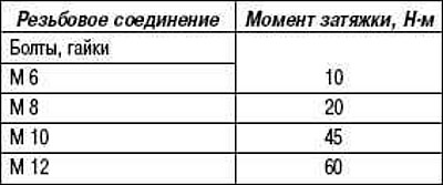
Tightening torques
Visitor comments