



Contents: Pressing out the sealing flange with…↓ Pressing in the sealing flange with…↓ Installing the oil seal with the…↓ Installing the mounting device with…↓ Screwing the mounting device to the…↓ Checking the mounting position of…↓
Pressing out the sealing flange with the sensor wheel
Remove the gearbox.
Remove the flywheel.
Remove the intermediate plate.
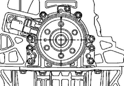
Fig. 2.263. Setting the crankshaft to TDC
Set the crankshaft to the TDC position of the cylinder as shown in Figure 2.263.
Remove the oil pan.
Note: To make the installation operations more clear, they are shown with the engine removed.
Note: The installation operations with the engine installed and the gearbox removed are the same.
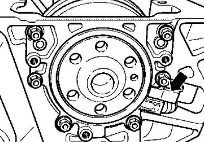
Fig. 2.264. Removing the engine speed sensor
Remove the engine speed sensor (fig. 2.264).
Remove the sealing flange mounting bolts.
Note: The sealing flange and sensor wheel are pressed out of the crankshaft together with three M6x35 mm bolts.
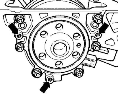
Fig. 2.265. Sealing flange fastening bolts
Screw three M6 x 35mm bolts into the threaded holes of the sealing flange (fig. 2.265).
Alternately screw (maximum one 1/2 turn (180°) on each bolt) the bolts into the sealing flange and press it out together with the sensor wheel from the crankshaft.
Pressing in the sealing flange with the sensor wheel
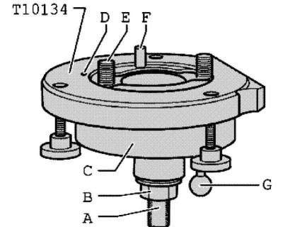
Fig. 2.266. Mounting device: A – pressure surface; B – hex nut; C – mounting cup; D – locking pin; E – Allen screw; F – guide pin for diesel engines (black handle); G – guide pin for petrol engines (red handle)
The mounting device is set in the correct position relative to the crankshaft by means of a guide pin that enters the crankshaft hole (fig. 2.266).
Note: The sealing flange with PTFE gland has a support ring of the working edge. This support ring functions as a mounting sleeve, therefore it is prohibited to remove it before installation.
Note: Once removed from the packaging, the flange and sensor wheel must not be separated or rotated.
Note: The sensor wheel is installed in the mounting position by locking it onto the pin of the mounting device.
Note: The sealing flange and oil seal are one element and can only be replaced together with the sensor wheel.
Installing the oil seal with the sensor wheel on the mounting fixture (A)
Unscrew hex nut B almost to the clamping surface A of the lead screw.
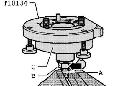
Fig. 2.267. Installing the mounting device in a vice
Clamp the mounting fixture by the clamping surface A of the lead screw in a vice (fig. 2.267).
Press mounting cup C down until it rests on hex nut B.
Tighten the hex nut onto the lead screw until the inside of the mounting fixture and the mounting cup are at the same level.
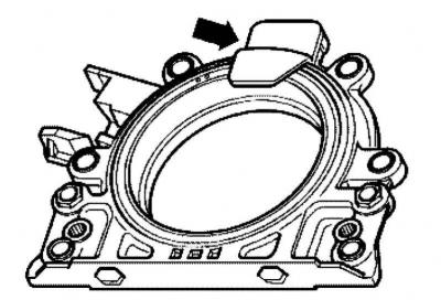
Fig. 2.268. Protective clip
Remove the protective clip from the new sealing flange (fig. 2.268).
Note: It is prohibited to remove the sensor wheel from the sealing flange or rotate it.
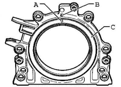
Fig. 2.269. Fixing hole and mark on the flange
The fixing hole A in the sensor wheel C must coincide with the mark B on the flange (fig. 2.269).
Place the flange face down on a clean, flat surface.
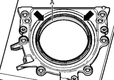
Fig. 2.270. Installing the support ring
Press the support ring of the working edge A downwards in the direction of the arrow until it lies on a flat surface (fig. 2.270).
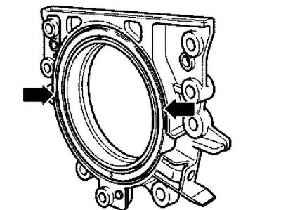
Fig. 2.271. Edge of the sensor wheel
The top edge of the sensor wheel and the front edge of the flange must be at the same level (fig. 2.271).
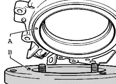
Fig. 2.272. Installing the flange on the mounting device
Place the flange face down on the mounting fixture so that the locking pin B fits into the hole A of the sensor wheel (fig. 2.272).
Note: Make sure the flange lies flat on the mounting fixture.
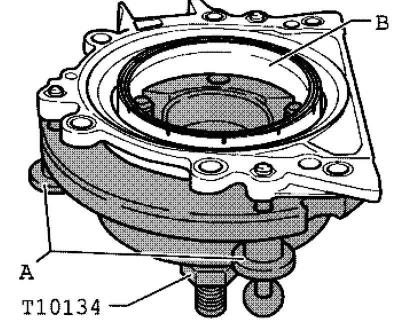
Fig. 2.273. Tightening the mounting fixture bolts
Press the flange and the support ring of the working edge B while tightening the three knurled bolts A onto the surface of the mounting fixture so that the locking pin cannot slip out of the hole in the sensor wheel (fig. 2.273).
Note: When installing the flange, ensure that the sensor wheel remains locked into the mounting fixture.
Installing the mounting device with a sealing flange on the crankshaft flange (B)
The crankshaft flange must be cleaned of oil and grease.
The engine is in the TDC position of cylinder 1.
Unscrew hex nut B to the end of the lead screw.
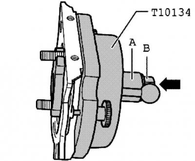
Fig. 2.274. Hexagonal nut and mounting cup
Press the lead screw of the mounting device in the direction of the arrow until the hex nut B rests on the mounting cup A (fig. 2.274).
Align the mounting cup with the flat side against the joint between the engine crankcase and the oil pan.
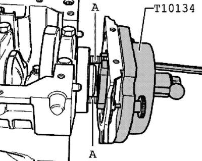
Fig. 2.275. Fastening the mounting device to the crankshaft flange
Secure the mounting fixture with Allen bolts A to the crankshaft flange (fig. 2.275).
Note: Screw the Allen bolts A approximately 5 threads into the crankshaft flange.
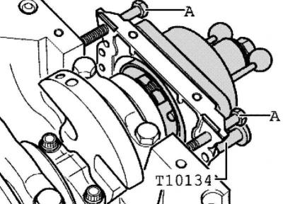
Fig. 2.276. Screwing in bolts to adjust the direction of the sealing flange
Screw two M7x35mm A bolts into the cylinder block to guide the sealing flange (fig. 2.276).
Screwing the mounting device to the crankshaft flange (C)
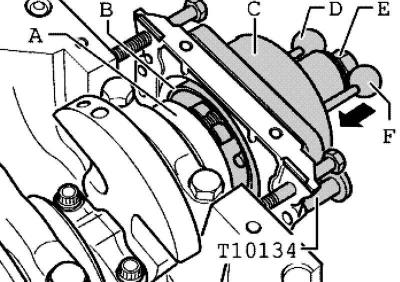
Fig. 2.277. Screwing the mounting device
Move the mounting cup C by hand in the direction of the arrow so that the support ring of the working edge B is pressed against the crankshaft flange A (fig. 2.277).
Insert the guide pin for diesel engines (black handle) F into the crankshaft hole. Due to this, the sensor wheel is finally installed in the mounting position.
Note: Guide pin for petrol engines (red handle) D must not be inserted into the threaded hole of the crankshaft.
Hand tighten both Allen bolts of the mounting fixture.
Thread hex nut E onto lead screw until it contacts mounting cup C.
Pressing the sensor wheel onto the crankshaft flange using the mounting tool (D)

Fig. 2.278. Tightening the hex nut of the mounting device
Tighten the hex nut of the mounting fixture using a torque wrench and socket to a tightening torque of 35 N·m (fig. 2.278).
Note: After tightening the hex nut to 35 Nm, there should still be a small gap between the cylinder block and the sealing flange.
Checking the mounting position of the sensor wheel on the crankshaft (E)
Unscrew the hex nut E to the end of the lead screw.
Remove both bolts A from the cylinder block.
Remove the three knurled bolts B from the sealing flange.
Remove the mounting fixture.
Remove the working edge support ring.
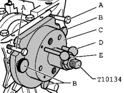
Fig. 2.279. The exact position of the sensor
The sensor wheel occupies the exact mounting position on the crankshaft when there is a distance A of 0.5 mm between the crankshaft flange A and the sensor wheel B (fig. 2.279).
Place the caliper against the crankshaft flange.
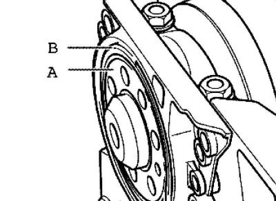
Fig. 2.280. Measuring the distance between the crankshaft flange and the sensor wheel
Measure the distance a between the crankshaft flange and the sensor wheel (fig. 2.280).
If the distance A is not enough, press the sensor wheel deeper.
When the distance a is reached, screw in the new sealing flange mounting bolts, alternating crosswise, with a torque of 15 Nm.
Install the engine speed sensor and tighten the mounting bolt to 5 N·m (fig. 2.264).
Install the oil pan.
Install the spacer plate.
Attach the flywheel with new bolts. Tighten the mounting bolts to a torque of 60 Nm + 1/4 turn (90°).
Visitor comments