
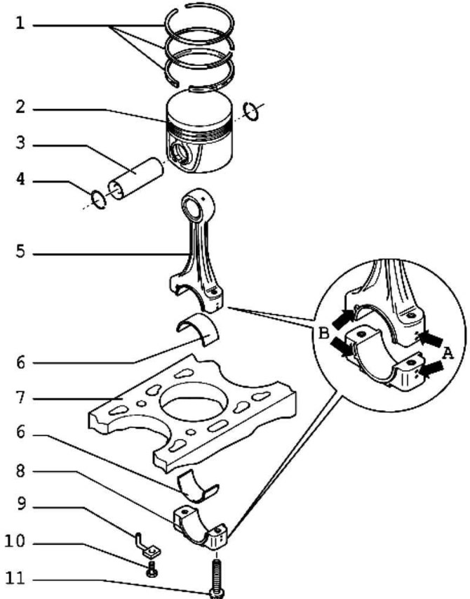
Pic. 2.285. Piston and connecting rod: 1 - piston rings; 2 - piston; 3 - piston pin; 4 - retaining ring; 5 - connecting rod; 6 - bearing shell; 7 – block of cylinders; 8 - connecting rod cover; 9 - oil injection nozzle; 10 - bolt 25 Nm; 11 - connecting rod bolt, 30 Nm + tighten 1/4 turn. (90°)
Note: For installation work, it is necessary to fix the engine with an engine and gearbox clamp on a mounting stand or on an engine and gearbox clamp.
Note: All bearing and working surfaces must be lubricated with engine oil before installation work.
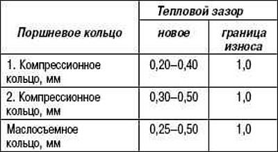
Checking the thermal clearance of the piston rings
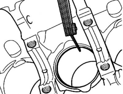
Pic. 2.156. Checking the thermal gap
Drive the piston ring from above, at right angles to the cylinder wall, to the bottom hole of the cylinder, at a distance of about 15 mm from its edge (pic. 2.156).
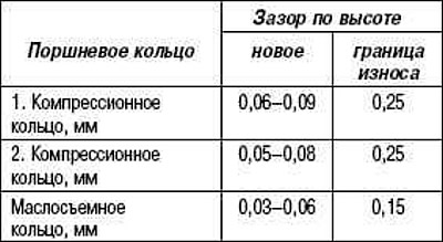
Checking the clearance of piston rings in height
Before checking, clean the annular groove.
Checking the cylinder diameter
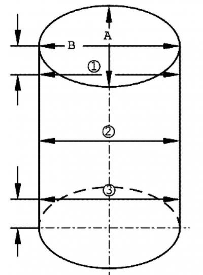
Pic. 2.159. Cylinder Diameter Test Diagram
Measure in three places with a cross the transverse distance A and the longitudinal distance B (pic. 2.159). Maximum permissible deviations from the nominal size - max. 0.10 mm.
Note: Do not measure cylinder diameters when the cylinder block is attached to the engine support of the rig, as this may cause incorrect results.
Mounting position and assignment of pistons to cylinders
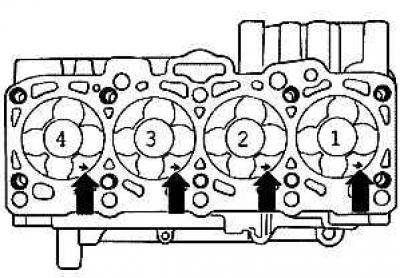
Pic. 2.286. Mounting position and assignment of pistons to cylinders
The arrows in figure 2.286 show the direction to the first cylinder (pic. 2.286).
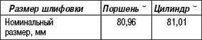
Piston and cylinder dimensions
Checking piston protrusion at top dead center
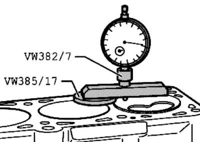
Pic. 2.287. Checking piston protrusion at top dead center
When installing new pistons or a new engine component, check the position of all pistons at top dead center. Depending on the protrusion of the pistons, install the appropriate cylinder head gasket according to the following table
Note: To measure the position of the pistons at top dead center, rotate the crankshaft clockwise.
Note: If different values are obtained from piston protrusion measurements, use the largest size for seal compatibility.
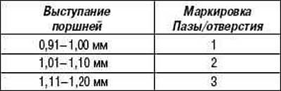
Cylinder head gasket marking
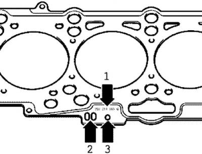
Pic. 2.288. Cylinder head gasket marking
Parts catalog number - 1.
Control code - 2 (does not contain important information).
Holes - 3.
Mounting position: marking upwards.
Note: The thickness of the cylinder head gasket to be installed depends on the protrusion of the pistons. When replacing, it is necessary to install a gasket with an identical marking 3.
Visitor comments