



Contents: Removal ↓ Installation ↓
Removal
Disconnect the ground wire from the battery with the ignition off.
Remove the engine cover.
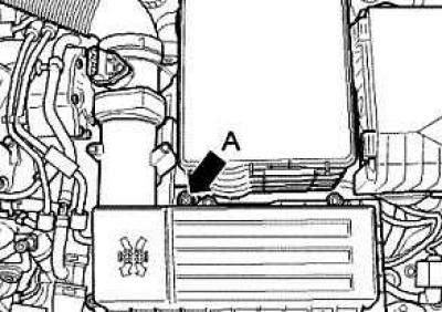
Fig. 2.253. Air filter housing mounting screw
Loosen screw A and pull the air filter housing up from the mount (fig. 2.253).
Remove the air filter housing with the air flow meter and connecting tube.
Remove the battery.
Remove the noise insulation screen.
Drain the coolant.
Disconnect the return and supply fuel lines, as well as the coolant pipe from the cylinder head.
Before removing the cylinder head, pump out the fuel using a hand vacuum pump with accessories and a container for pumping out liquid from the tandem type pump.
Remove the poly V-belt.
Remove the intercooler/intake manifold connecting hose.
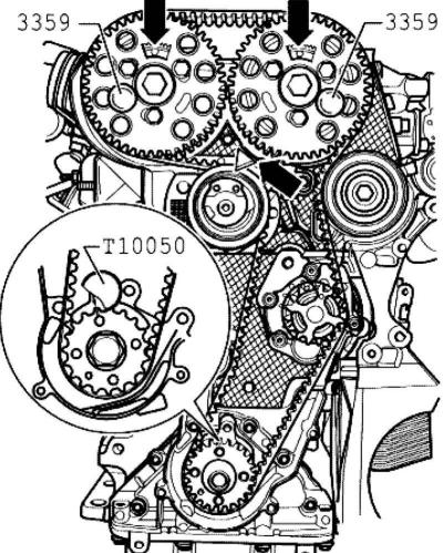
Fig. 2.294. Alignment of marks on the timing belt cover and camshaft
[The original text is available on the website: vwmanual]
Unscrew the torsional vibration damper and remove it from the crankshaft. Fix the crankshaft with a crankshaft lock or a crankshaft lock in the TDC position of the first cylinder (fig. 2.294).
Cars without a particulate filter
Unscrew the exhaust pipe from the turbocharger, unscrew the double clamp and remove the exhaust pipe.
Cars with particulate filter
Remove the diesel particulate filter.
Continuation of description of works for all cars
Remove the turbocharger mount and oil return line from the turbocharger.
Loosen the tension roller mounting nut and loosen the timing belt tension.
Remove the tension roller mounting nut.
Remove the camshaft gears and hubs.
Unscrew the Hall sensor on the cylinder head.
Remove the mounting bolts from the lower part of the timing belt cover on the cylinder head.
Unscrew the vacuum receiver and oil dipstick holder.
Remove the EGR system connecting pipe.
Remove the turbocharger oil feed line.
Remove/disconnect all other existing electrical wires from the cylinder head.
Disconnect all connecting, vacuum, inlet, coolant supply and outlet hoses from the cylinder head.
Remove the cylinder head cover.
Remove the roller arm shaft and the inner support module mounting bolts.
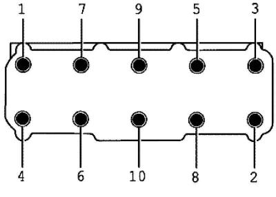
Fig. 2.302. Sequence of unscrewing the cylinder head mounting bolts
Observe the sequence when unscrewing the cylinder head mounting bolts (fig. 2.302).
Lift the cylinder head slightly and remove it from the engine past the timing belt cover.
Note: The timing belt tensioner roller remains on the engine mount.
Note: The cylinder head must be handled very carefully to avoid damage.
Installation
Place the cylinder head gasket with the marking facing up.
Note: Always replace the cylinder head bolts.
Note: When repairing, remove any remaining sealant from the cylinder head and cylinder block. Avoid creating long scratches or burrs. When using sandpaper, its grain size should be at least 100.
Note: Remove any sanding or grinding residue.
Note: The new cylinder head gasket should be removed from the packaging immediately prior to installation.
Note: Damage to the silicone layer and corrugated connections leads to loss of tightness.
Note: Before installing the cylinder head, remove the crankshaft lock or crankshaft stop and rotate the crankshaft against the direction of engine shaft rotation until all pistons are evenly positioned below TDC.
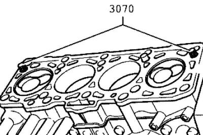
Fig. 2.303. Centering pins
For centering, screw the guide bolt into the outer holes on the suction side (fig. 2.303).
Note: When installing the cylinder head, the tension roller must be installed on the spacer bolt.
Install the cylinder head, insert the remaining 8 cylinder head mounting bolts and tighten them by hand.
Remove the guide bolt with a screwdriver through the hole and install the cylinder head bolts.
Then tighten the cylinder head bolts in 4 stages in the following sequence:
- 1 - tighten with a torque wrench;
- - stage 1 = 35 Nm;
- - stage 2 = 60 Nm;
- 2 - then turn with a regular key;
- - stage 3 = turn 1/4 turn further (90°);
- - step 4 = turn an additional 1/4 turn (90°).
Secure the lower part of the timing belt cover to the cylinder head.
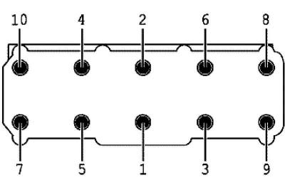
Fig. 2.304. Sequence of tightening the cylinder head bolts
Screw the Hall sensor to the cylinder head.
Install the hubs and camshaft gears.
Lock the camshafts using diesel fuel injection pump locking pins
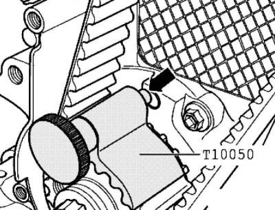
Fig. 2.301. Lock pin
Rotate the crankshaft in the direction of engine shaft rotation and set it to TDC, fix the crankshaft with a crankshaft lock or crankshaft lock (fig. 2.301).
Center the camshaft gears in the longitudinal grooves.
Place the timing belt first on the exhaust camshaft gear, then on the intake camshaft gear.
Install the tension roller retaining nut.
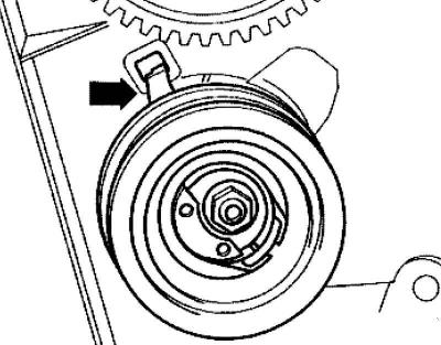
Fig. 2.298. Correct seating of the tension roller
Note: Make sure the tension roller is seated correctly in the rear of the timing belt cover (fig. 2.298Note:).
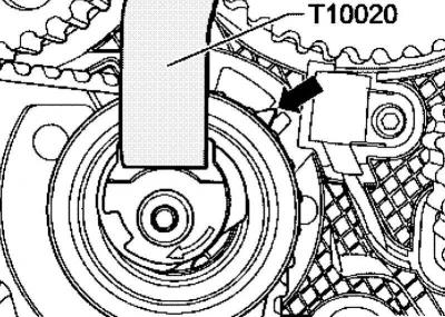
Fig. 2.299. Rotation of the tension roller
Then rotate the tension roller with the impact wrench in the direction of the arrow until the arrow is in the middle of the gap of the support plate (fig. 2.299).
Make sure that the fastening nuts do not turn while doing this.
Lock the tension roller in this position and tighten the tension roller fastening nut as described below to a torque of 20 Nm and turn it further by 45° (1/8 turn).
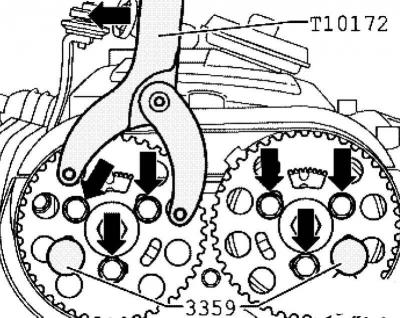
Fig. 2.300. Installing the counter support
Install the counter support as shown in Figure 2.300. Press the counter support in the direction of the arrow and clamp the camshaft gears.
Tighten the camshaft gear mounting bolts in this position to 25 Nm.
Remove the locking pins, crankshaft lock or crankshaft retainer.
Make at least 2 crankshaft revolutions in the direction of engine shaft rotation and set the first cylinder again before the top dead center position.
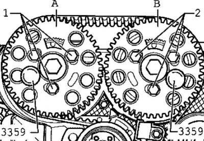
Fig. 2.296. Fixing the hubs with pins
Secure hub A against rotation in the direction of the engine shaft using a locking pin (fig. 2.296).
Check that hub B is secured with the locking pin.
The crankshaft was fixed using a crankshaft lock.
The tension roller arrow should be in the middle or max. 5 mm to the right of the support plate gap.
Further installation is carried out in the reverse order. In this case, the following must be taken into account.
Install the roller lever axle.
Install the cylinder head cover.
Install the oil supply line.
Install the poly V-belt.
Fill with coolant.
Perform a test drive and interrogate the fault memory.
Visitor comments