
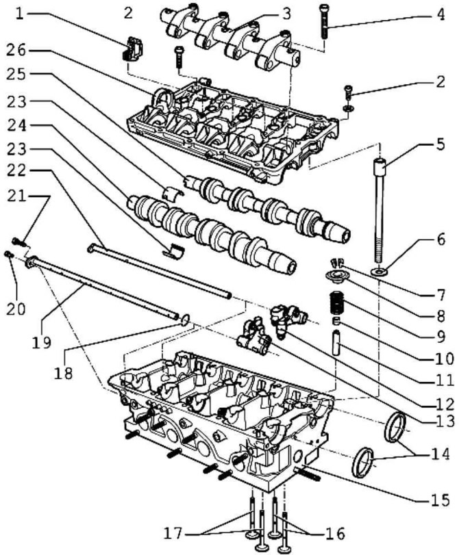
Pic. 2.305. Valve mechanism: 1 - cable holder, 10 Nm; 2 - bolt 20 Nm; 3 – axis of roller levers; 4 - bolt 20 Nm + turn 1/4 turn. (90°); 5 – a bolt of a head of the block of cylinders; 6 - washer; 7 - conical cracker; 8 - valve spring plate; 9 - valve spring; 10 - valve stem seal; 11 - valve guide sleeve; 12 - roller lever-inlet; 13 - roller lever-release; 14 - stuffing box; 15 – a head of the block of cylinders; 16 - inlet valves; 17 - exhaust valves; 18 – O-ring; 19 - plug-in axles; 20 - bolt 10 Nm; 21 - locking bolt; 22 - plug-in axles; 23 - bearing shell; 24 - exhaust camshaft; 25 - intake camshaft; 26 - support module
Mounting position of mixing tube
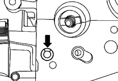
Pic. 2.306. Connecting tube groove
Groove of connecting tube points up (pic. 2.306).
Checking the axial clearance of the camshaft
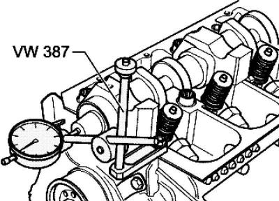
Pic. 2.307. Checking the axial clearance of the camshaft
Check the camshaft end play.
Limit tolerance max. 0.15 mm.
Visitor comments