
Removing
Remove the engine cover.
Remove the air filter housing with air mass meter and connecting tube.
Remove poly V-belt.
Remove the EGR cooler and bypass cover (cooling system hoses may remain connected) and put them aside
Remove the EGR cooler mounting.
Remove the toothed belt from the camshaft gears.
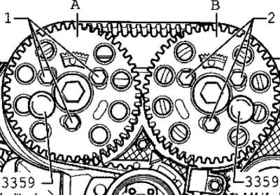
Pic. 2.296. Fixing hubs with pins
Unscrew the fixing bolts 1 and 2 of the camshaft gears (pic. 2.296).
Remove the camshaft gears from the hubs.
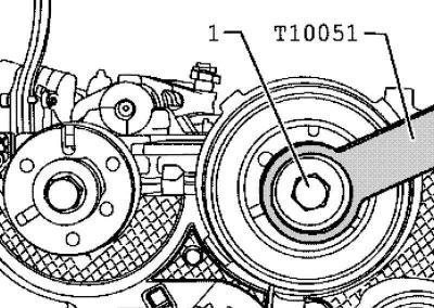
Pic. 2.314. Unscrewing the hub mounting bolt
Unscrew the fixing bolt 1 hub (pic. 2.314).
To do this, use a counter support.
Loosen the hub mounting bolt about 2 turns.
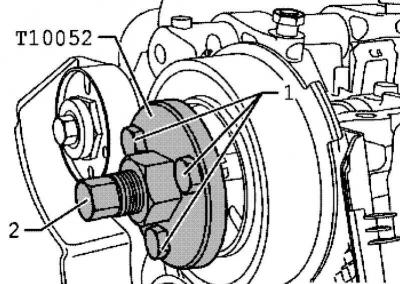
Pic. 2.315. Installing the puller on the hub
Install the puller, guiding it towards the hub holes (pic. 2.315).
Tighten fixing bolts 1.
Remove the hub by evenly tightening the puller 2, as a result the hub will separate from the camshaft cone.
Note: When doing this, secure the puller with a wrench 30.
Remove the hub from the camshaft cone.
Remove the exhaust camshaft hub in the same way.
Remove the cylinder head cover.
Remove the tandem pump.
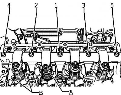
Pic. 2.316. Adjustment screw locknuts
Unscrew the locknuts of the adjusting screws a and unscrew the adjusting screws until the corresponding rocker arm rests on the pusher spring of the unit injector (pic. 2.316).
Screw bolts 5-1 evenly from outside to inside and remove the axle of the roller levers.
Remove the inner fixing bolts on the back of the toothed belt cover.
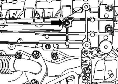
Pic. 2.317. Top fixing bolt of the bypass cover holder
Unscrew the upper fixing bolt of the holder of the bypass cover and the cooler of the exhaust gas recirculation system (pic. 2.317).
Remove the cable connection of the unit injectors and glow plugs.
Screw in the remaining 15 bolts of the support module evenly from the outside to the inside.
Unscrew the release bolts 15 of the frame by hand counterclockwise until it stops.
Install the frame on the support module as shown and tighten the fixing bolts 10 with a torque of 10 Nm.
Frame installation
Turn the release bolts clockwise by hand until they rest against the cylinder head bolts.
Then evenly screw in the release bolts in the sequence indicated on the bolt heads until the support module is separated from the cylinder head.
Remove the support module.
Remove the distributors.
Installation
Install the bearing module and roller arm axle.
Note: When installing the camshafts, the cams for the first cylinder must point upwards.
Note: Do not interchange previously used bearing shells (mark when removing).
Note: When installing the camshafts, make sure that the stop toes of the bushings in the bearing caps and in the cylinder head are correctly installed.
Note: Apply silicone sealant to the seating surfaces between the bearing module and the cylinder head.
Note: Lubricate the bearing surface with engine oil.
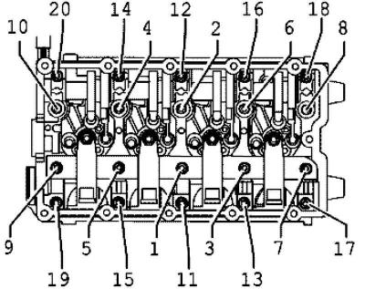
Pic. 2.318. The procedure for tightening the camshaft bearing bolts
Evenly tighten the bolts 1–20, starting with the inner ones, as shown in Figure 2.318. Tightening torque 20 Nm.
Then turn the roller arm axle bolts 9 1/4 turn. (90°) pic. 2.316).
Install the camshaft seals.
Install the hubs on the camshafts.
Tighten the fixing bolts 1 of the hubs (pic. 2.314). Tightening torque 100 Nm.
To do this, use a counter support.
Install the camshaft gears to the hubs.
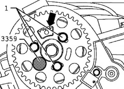
Pic. 2.319. The position of the gear sector
Note: The gear sector of the camshaft gear must be at the top (pic. 2.319 Note:).
Insert by hand the fixing bolts 1 and 2 without play into the camshaft gear (pic. 2.296).
Lock the hubs with the injection pump locking pin.
Install the toothed belt and adjust the valve timing.
Install a tandem pump.
Install the cylinder head cover.
Install poly V-belt.
Note: After installing new roller arms, the engine must not be started for approximately 30 minutes. Hydraulic lifters must be deposited (otherwise the valves will come into contact with the pistons).
Visitor comments