



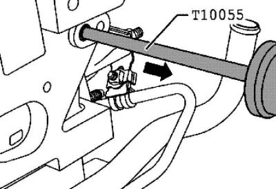
Fig. 2.309. Installing the puller into the insert axle
Screw the puller into the insert axle (fig. 2.309).
Remove the insert axle by tapping it lightly.
Installation is carried out in reverse order, taking into account the following.
Note: Do not interchange used roller levers.
Insert the insert shaft into the cylinder head and roller lever.
The insert axle must fit snugly against the cylinder head.
Valve sizes
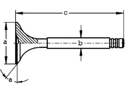
Fig. 2.310. Valve dimensions
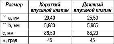
Note: Valves must not be machined. Only lapping is permitted.
Visitor comments