



Contents: Removal ↓ Installation ↓
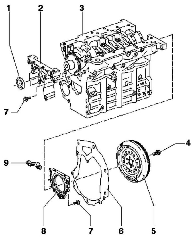
Fig. 2.260. Sealing flange and flywheel: 1 – oil seal; 2 – sealing flange; 3 – cylinder block; 4 – bolt 60 Nm + tighten by 1/4 turn (90°); 5 – flywheel; 6 – intermediate plate; 7 – bolt 15 Nm; 8 – sealing flange with sealing ring; 9 – engine speed sensor
Removal
Remove the poly V-belt.
Remove the timing belt.
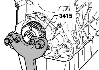
Fig. 2.138. Fixing the crankshaft sprocket
Remove the crankshaft gear. Secure the gear with a counter support (fig. 2.138).
Screw the central bolt to the seal puller guide by hand until it stops against the crankshaft.
Unscrew the inner part of the seal puller two turns (about 3 mm) from the outer part and secure with a knurled bolt.
Lubricate the threaded head of the oil seal puller.
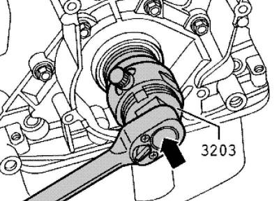
Fig. 2.140. Turning the inner part of the puller
Screw the puller in, pressing hard, as deep into the seal as possible (fig. 2.140).
Loosen the knurled bolt and rotate the inside of the puller against the crankshaft until the seal is removed.
Installation
Remove any remaining oil from the crankshaft journal using a clean rag.
Note: The sealing lip does not require additional lubrication.
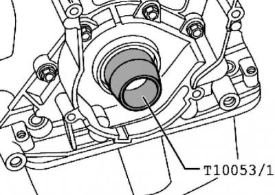
Fig. 2.141. Installing the guide bushing
Install the guide bushing onto the crankshaft journal (fig. 2.141).
Slide the oil seal through the guide sleeve onto the crankshaft journal.
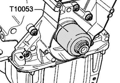
Fig. 2.261. Pressing in the oil seal
Press the seal in using the mounting sleeve and the central bolt until it stops (fig. 2.261).
Remove the crankshaft gear. To do this, secure the gear with a counter support (fig. 2.138).
Tighten the central bolt to 120 Nm + 1/4 turn further (90°) (additional tightening can be performed in several stages).
Note: The thread and flange must be free of grease.
Install the timing belt.
Install the poly V-belt.
Visitor comments