
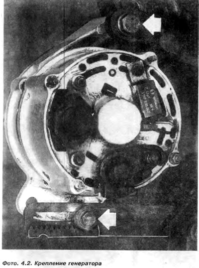
2. Loosen the bottom bolt securing the alternator to the slotted movable bracket (photo 4.2).
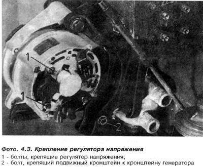
3. Loosen bolt 2 that secures the bracket with an oblong hole to the generator bracket (photo 4.3).
4. Tilt the alternator towards the engine and remove the V-belt.
5. Put a new belt on all pulleys and pre-tighten the belt by hand.
6. It is easy to tighten the bolt that secures the generator to the movable bracket.
7. Insert a large wrench or into the tires between the alternator and the housing in order to tighten the V-belt while lifting the alternator.
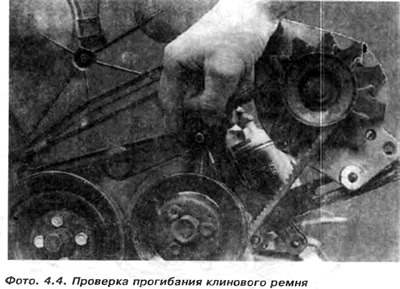
The belt is considered correctly tensioned when it is bent by 5 mm under finger pressure or 2 mm for a new belt (photo 4.4)
8. Tighten the bolt that secures the generator to the movable bracket and the second bolt that secures the movable bracket to the generator bracket.
If for the rotation of the generator it was necessary to loosen the upper bolt above the generator, then it should also be compressed.
9. Since 4.85, the generator mount has been changed. The tension of the V-belt is facilitated by means of a bolt and nut that rolls on the gear rack of the movable holder (photo 4.2).
When installing a belt that has already been used, the nut must be tightened to a torque of 4 Nm, and when installing a new belt, to a torque of 8 Nm. Hold the nut in this position and tighten the fixing bolt with a torque of 40 Nm.
10. Screw the movable bracket to the body with a torque of 25 Nm.
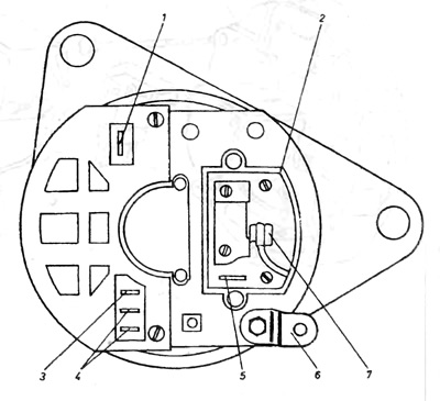
Pic. 4.4. View of the rear cover of the Motorola generator
1 - (Tue) for anti-interference capacitor; 2 - voltage regulator; 3- (D+) to the signal light; 4 - (WT); 5 - (DI-) green voltage wire; 6 - ground clamp; 7- (Dt) red wire for voltage regulator.
Visitor comments