
Rotor 11 (pic. 4.3) together with the excitation winding rotates inside the fixed stator winding 13 at a double speed relative to the motor. The excitation current flows through the carbon brushes 16 and the copper rings of the rotor to the excitation winding. This creates a magnetic field. Along with the rotation of the rotor, the position of the magnetic field in relation to the stator winding is constantly changing. Due to this, an alternating three-phase current is formed in the stator winding, which is replaced by a constant one in the diode rectifier 18. The diodes are fixed on the plate. Depending on the state of charge of the battery, the voltage regulator changes the amount of charging current by turning the excitation current on and off. At the same time, the regulator keeps the charging voltage constant at the application level of 14.V, regardless of the engine speed.
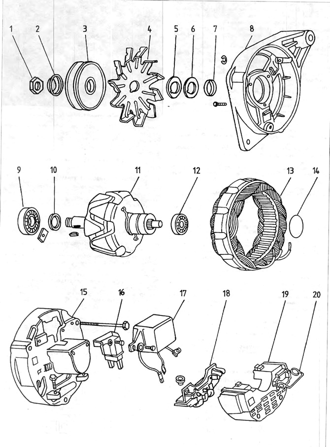
Pic. 4.3. Motorola alternator
1 - pulley nut; 2 - washer, 3 - pulley; 4 - fan; 5, 6 and 7 - washers; 8 - front bearing cover; 9 - ball bearing; 10 - remote washer; 11 - rotor; 12 - ball bearing; 13 - stator winding; 14 - O-ring type o-ring; 15 - back cover; 16 - brush holder; 17 - voltage regulator; 18 - plate with diodes; 19 - plastic cover; 20 - spring latch.
Visitor comments