



2. Check the stator winding by connecting one clamp of the ohmmeter to the body, and the second one in turn to the three ends of the winding. The ohmmeter should show infinity each time. Then it is necessary to check the resistance of the windings.
The connected ohmmeter between terminals 1-3, 1-2 and 2-3 should show resistance (figure 4.6):
0.25...0.28 Ohm - for 35 A generators
0.14..0.16 Ohm - for 55 A generators
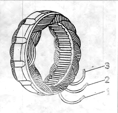
Figure 4.6. Generator - stator winding
1, 2 and 3 - ends of stator windings.
3. Sliding rings that are scratched or burnt must be re-sharpened.
4. The generator diodes must be checked separately by connecting the ohmmeter ends to the diode body and to the diode clamp. When the diode is shorted, the ohmmeter shows resistance close to zero in both directions. During breaks, the ohmmeter shows more than 100 kOhm in both directions. The resistance in the reverse direction of a serviceable diode should be more than 100 kOhm.
Visitor comments