
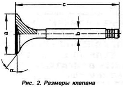
Valves are not subject to regrinding, only their grinding is allowed.
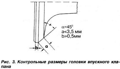
The control sizes of a head of the inlet valve are given on fig. 3.
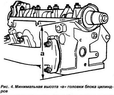
WARNING: Before repairing the cylinder head, make sure that the size «A» (pic. 4) not less than 139.5 mm.
Regrinding of valve seats
When repairing engines with loose valves, it is not enough to regrind the seats, lap in or replace the valves themselves. It is also necessary to check the wear of the guide bushings, especially if the engine is removed from the vehicle after a significant mileage.
Valve seats are reground only to the extent necessary to restore the normal appearance of the bearing surface. Before performing the operation, it is necessary to calculate the maximum thickness of the metal layer to be removed when regrinding the saddle. If the actual removal is greater than the calculated value, then the valve clearance hydraulic compensation function will be disrupted, and the cylinder head will have to be replaced.
Calculation of the maximum thickness of the removed metal layer when regrinding valve seats
NOTE: If a valve is replaced during a repair, a new one is taken for measurement.
After inserting the valve, press it firmly against the seat.
measure distance «A «(pic. 5) between the end face of the valve stem and the upper plane of the cylinder head.
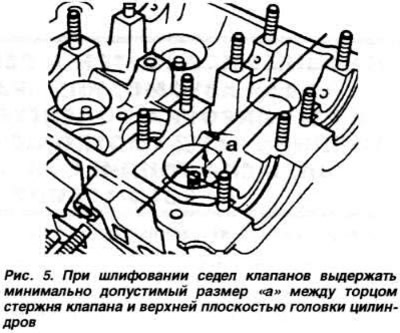
Calculate Size «b» the limiting thickness of the removed metal layer as the difference between the measured distance «A» and the minimum allowable control size «With» according to the formula
b = a - c
Minimum allowable control dimensions: for inlet valves - 33.9 mm; for exhaust valves - 34.1 mm.
Example:
Measured distance a=34.8 mm.
The minimum allowable control dimension c=34.1 mm. The limiting thickness of the metal layer to be removed is b=0.7 mm.
Control dimensions for regrinding valve seats
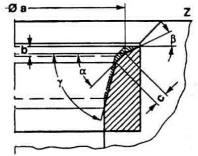
Pic. 6. Dimensions for grinding the inlet valve seat: a - seat diameter, a = 38.3 mm; b is the maximum allowable metal removal during regrinding; c - size, which should not exceed 1.4 mm (if necessary, the insert ring of the seat is repaired using a cutter that provides a specified correction angle of 75°); Z - the lower plane of the cylinder head; α — valve seat chamfer angle, ∠ α=45°; β is the upper correction angle, ∠ β=30°; γ is the lower correction angle. ∠γ =75°
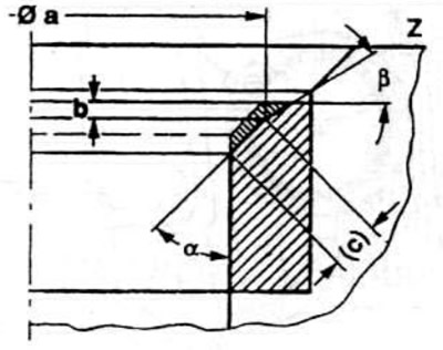
Pic. 7. Dimensions for grinding the exhaust valve seat: a - seat diameter, a = 33.5 mm; b is the maximum allowable metal removal during regrinding; c - size, which should not exceed 2.0 mm (if necessary, the insert ring of the seat is repaired using a cutter that provides a specified correction angle of 75°); Z - the lower plane of the cylinder head; α — valve seat chamfer angle, ∠ α=45°; β is the upper correction angle, ∠ β=30°.
Replacing the guide bushings of the cylinder head
Pressing out worn guide bushings is carried out using tool 10-206 (pic. 8). mounted on the side of the camshaft. Lubricate the new bushing with engine oil and press it in with the same tool, also from the side of the camshaft. The cylinder head must be cold. Pressing is carried out up to the sealing belt.
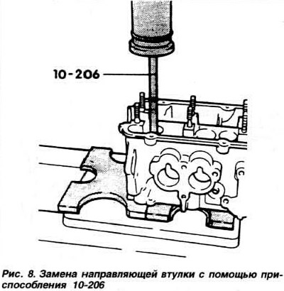
WARNING: After the guide bush rests against the belt, the pressing force should not be increased above 1 ton, otherwise the bushing may be destroyed.
After replacing the guide sleeves, be sure to grind the valve seats, paying attention to the minimum allowable control dimension.
Insert the new valve into the guide bush so that the end of the valve stem is flush with the edge of the guide bush, and determine the gap between the stem and guide bush using tool VW387 with an indicator, resting the indicator stem against the valve head (pic. 9).

Replace the guide bushings if the indicator reading is greater than 1.0 mm for the inlet valve bushings and 1.3 mm for the exhaust valve bushings.
Removal and installation of valve stem seals
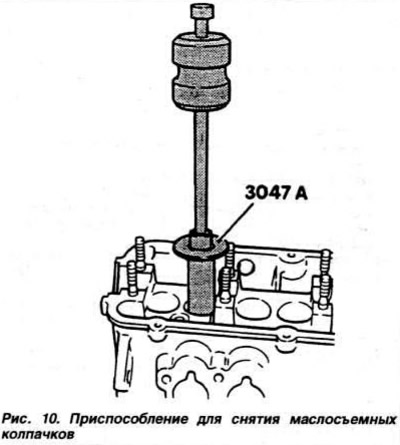
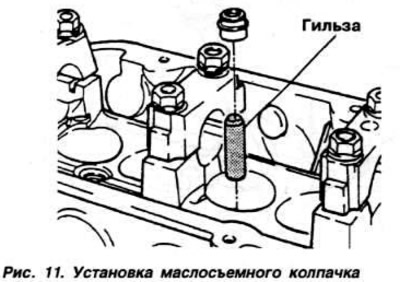
The valve stem seals are removed using tool 3047A, the action of which is clearly seen in fig. 10. Installation of valve stem seals is carried out using a special plastic sleeve worn on the valve stem. The cap is lubricated with engine oil and carefully pushed first onto the sleeve and then onto the valve guide (pic. eleven).
Visitor comments