
Valve springs
An accurate check of the valve springs requires the use of a special measuring tool. If there is none, you can do the following:
Compare the removed spring with the new one. If the old spring is shorter than the new one, then it is worn out and must be replaced along with the rest.
Place the springs on a flat surface (glass) coils pressed down. Attach a square to the spring and measure the distance from the top edge of the spring to the square. If it is greater than 2.0 mm, then the spring is unacceptably bent and needs to be replaced.
Place the springs on a flat surface (glass) coils pressed down. Attach a square to the spring and measure the distance from the top edge of the spring to the square. If it is greater than 2.0 mm, then the spring is unacceptably bent and needs to be replaced.
Valve guides
Clean the valve guides with a rag soaked in gasoline or acetone. After cleaning, insert the appropriate valve into the holes.
Attach the indicator to the mating plane of the block head with a special clip (pic. 46). Slide the valve out of the sleeve until the end of the valve stem is hidden in the hole in the sleeve.
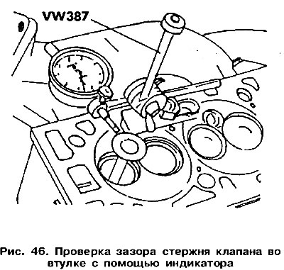
While rocking the valve in a direction perpendicular to the axis of the valve stem, take the sensor readings. If they exceed 1.0 mm for intake valves and 1.3 mm for exhaust valves, the bushings must be replaced.
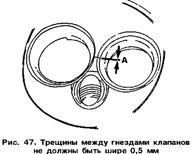
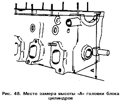
Before replacing bushings, the general condition of the block head should be assessed. Head with small cracks between valve seats (pic. 47) or between the valve seat and the first thread in the spark plug hole may be reused or ground if the cracks are not wider than 0.5 mm. Size «A» after repair sanding (pic. 48) cannot be less than 135.6 mm.
 |  |
Attention! If the valve liner has been replaced, the valve seats must be machined.
Before pressing the guide bushing out of the block head, see if there is a support flange at its end (see arrow in fig. 45). A bushing with a flange is pressed out from the side of the combustion chamber, and without a flange - from the side of the camshaft. The old guide bush is pressed out using a rod of a suitable diameter. To facilitate the work, you can heat the head. The rod must end with a thinner shank, which is inserted into the hole in the sleeve.
At the same time as replacing the guide bushings, the valves must also be replaced. Valve seats need to be reground.
Lubricate the new bushings with plenty of oil and press into the cold head from the side of the camshaft until the support flange is level with the mating plane of the head of the block. It is impossible to press in further, since the flange can be cut off.
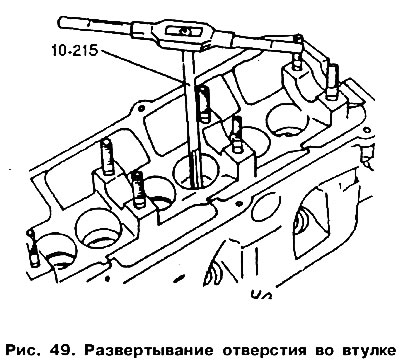
After pressing, unfold the holes of the bushings using a special reamer «10-215» (pic. 49). The bushing holes for the intake and exhaust valves must be reamed to a size of 8.0 mm. In this case, a normalized clearance will be maintained between the sleeve and the valve.
Valve seats
If the camshaft bed is worn out, then you can use a rebuilt block head. In this case, valve seat preparation is not required.
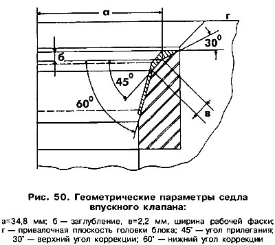 | 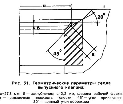 |
Check the seat wear on each valve. Minor surface wear can be corrected with a 45°cone cutter. Heavily worn seats must be reground. The values of the geometric parameters of the valve seats are shown in fig. 50 and 51. The design of valve seats in carburetor engines and engines with fuel injection is the same. It should be ensured that the working chamfer is not too deep into the body of the block head. To verify this, you must perform the following steps:
- insert the valve into the guide sleeve, pressing the valve head against the seat in the chamfer area;
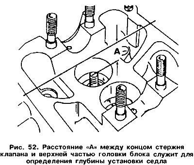
- measure the distance «A» (pic. 52) between the end of the valve stem and the upper mating plane (see fig. 50, 51) block heads.
- determine the allowable depth of the valve (designated as «b» in fig. 50 and 51), based on the value of the measured distance «A» and the fact that the minimum distance from the end of the valve stem to the upper mating plane of the block head is 35.8 mm for the intake valve and 36.1 mm for the exhaust valve.
When processing, you must adhere to the following recommendations.
When replacing valve guides, the valve seats must be machined, which is done as follows. The actual surface of the girdle is machined with a milling cutter with an angle of 30° (inlet valve) or 45° (Exhaust valve), and then the desired width of the working belt is formed (2.2 mm) due to the processing of the upper part with a 45°cutter (inlet valve) or 30° (Exhaust valve) and the bottom with a 60°cutter (for inlet valves only).
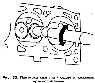
After processing the working chamfers of the seats, the valves should be ground to them. To do this, cover the surface of the seat with lapping paste mixed with engine oil, and insert the valve into place, lubricating its stem with engine oil. Attach a lapping tool to the valve and rotate the valve in both directions (pic. 53), slightly pressing the valve to the seat. Work at the initial stage can be facilitated if the valve is rotated with a drill. Finish lapping using only clean engine oil.
After lapping is complete, remove the paste and clean all surfaces. Inspect seat and valve seat surfaces. On both surfaces there should be a continuous opaque ring with a width equal to the width of the working bevel.
On the working chamfer of the valve, make a few marks in a circle with a pencil in about 1 mm. Insert the valve into the sleeve and push it into the seat. Slightly pressing on the valve, turn it 90°.
Remove the valve and make sure that the pencil marks on the work belt are gone. Start assembling the head. Otherwise, you should continue processing the mating surfaces and, as a last resort, install a new or restored cylinder head.
Valves
Minor damage to the valve face can be removed by lapping the valve against the seat as described previously.
Check valve wear (pic. 55), considering the differences between intake and exhaust valves. Valves with severe wear must be replaced.
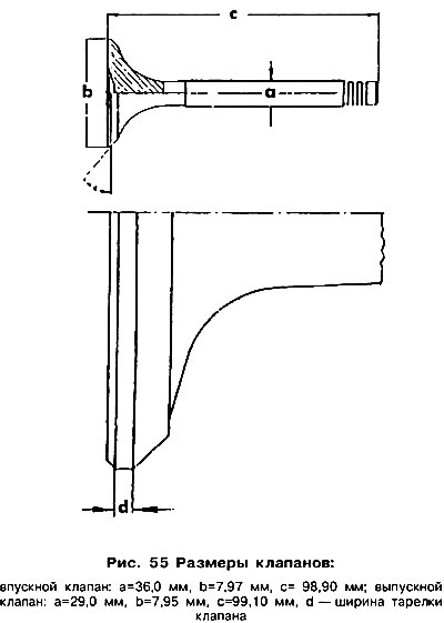
If signs of wear appear on the end of the valve stem, you can grind it, remembering that the layer of metal removed should not exceed 0.5 mm.
Valve discs must not be ground. Damaged valves can only be ground in or replaced with new ones.
Cylinder head
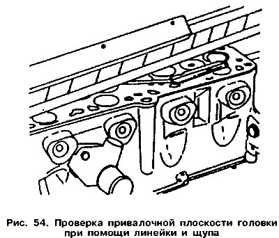
Thoroughly clean the mating surfaces of the block head and engine block, and then check whether the block head is deformed. To do this, put a special rail on the mating plane of the block head, as shown in Fig. 54, and using feeler gauges, determine the degree of warping of the block head along, across and along the diagonals of the mating plane. If the gap is not much more than 0.10 mm, then the head should be given for grinding. With a large non-flatness of the surface, a mandatory replacement of the head is required. After grinding, the height of the block head should not be less than 135.6 mm. The location for measuring the block head height is shown in Figure 48.
Camshaft
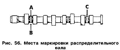
The camshaft is marked in a certain way, shown in Figure 56, depending on the type of engine:
- in a carbureted engine «HZ» the camshaft is not marked;
- in a carbureted engine «MN» and type «NU» the camshaft has a cast belt between the cams of the first cylinder, of a larger diameter than the bearing neck, indicated in fig. 56 letter «D»;
- in an engine with an injection system, the camshaft has two cast belts between the cams of the first cylinder, indicated in Fig. 56 by the letter «IN», but there is no cam on this shaft «WITH» to drive the fuel pump.
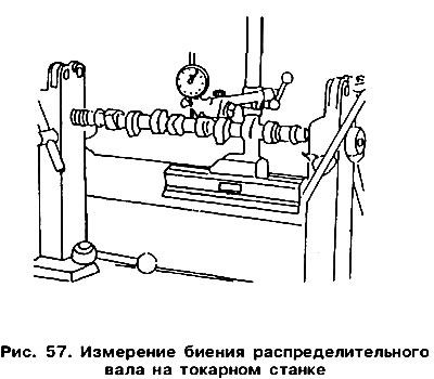
Install the outer camshaft journals on two prisms located on the measuring plate, or clamp it in the centers on a lathe (rice 57). Attach an indicator to the central neck of the shaft. Slowly rotating the camshaft, read the indicator. If the readings exceed 0.10 mm, the shaft is deformed and needs to be replaced. Check the shaft for visible defects.
In order to check the radial clearance in the shaft bearings, a calibrated plastic wire must be used «Plasligage».
The check should be carried out without installing pushers as follows:
Clean the covers and camshaft bed and install the shaft in place.
Lay a piece of calibrated wire along the axis of the shaft on each bearing journal of the shaft and install the bearing caps according to their numbers (see fig. 42). Tighten the cover fastening nuts evenly, starting from the middle towards the edges, with a force of 6 Nm, and then tighten them by another 90°. The camshaft cannot then be rotated.
Turn away nuts of fastening of covers of bearings in reverse order and remove covers. Compare the width of the calibrated wire segments with the existing ruler-template. If the clearance in any bearing exceeds 0.10 mm, then the wear limit of the bearing and camshaft has been reached, which will require the replacement of the shaft, and often the cylinder head.
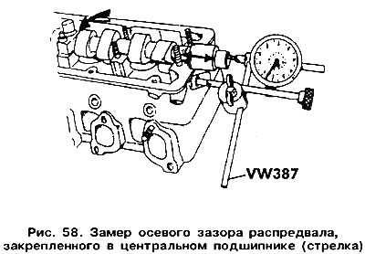
To determine the axial play, it is necessary to install the camshaft in the block head (without pushers) and secure with the center bearing cap. Place the block head on a flat surface and, after attaching the indicator to the front of the block head, (pic. 58) move the shaft along the axis. The axial play must not exceed 0.15 mm. A higher value indicates wear on the thrust surface of the bearing cover.
Visitor comments