



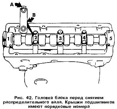
Clamp the head in a vice by the bracket screwed to the exhaust manifold studs. Gradually and alternately on each side, unscrew the bolts securing the bearing caps number 1, 3 and 5 (see figure 42). Also unscrew both bolts from the outer bearing cover. Loosen the nuts securing the bearing cover number 2 and number 4 by two turns, "crosswise", and then unscrew. Remove both covers and take out the camshaft. Immediately inspect the liners and the marks used for their correct installation. The projection "A", indicated in Figure 42, is located on the intake manifold side, and the numbers on the covers "B" should be readable when viewed from the exhaust manifold side.
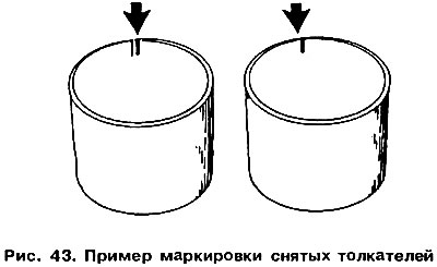
Remove the tappets. They cannot be interchanged and should therefore be marked, for example with strokes on the inside (first tappet - one stroke, second - two, etc. - see Figure 43). The tappets should be placed with the surface in contact with the camshaft cam down, so that oil does not leak out from the inside.
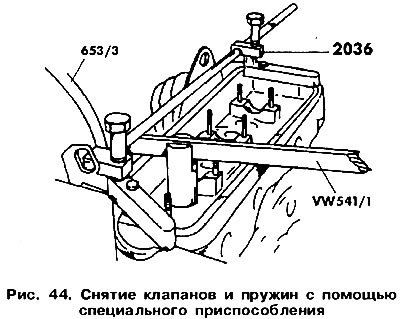
To properly disassemble the valve mechanism, you will need a special device, shown in Figure 44. Use the rod of the VW541 / 1 device to press on the upper plate, compressing the spring so much that you can remove the crackers. To remove the valves, you can use a short section of pipe that is installed on the upper plate. Support the valve head well. Release the crackers by lightly hitting the pipe with a hammer. They will remain inside the pipe, so you should be careful not to lose them.
Remove the plates and springs. Remove the oil deflector cap and discard it immediately, as it must be replaced with a new one. Figure 45 shows the remaining units and parts of the cylinder head after removing the camshaft.
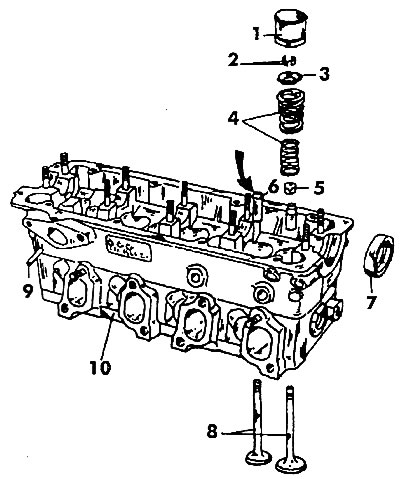
Figure 45. Cylinder head components after removing the camshaft: 1 - hydraulic tappet, 2 - crackers, 3 - upper spring plate, 4 - valve springs, 5 - oil scraper cap, 6 - valve guide sleeve, 7 - camshaft oil seal, 8 - valves, 9 - fuel pump tappet, 1 O - cylinder head
Visitor comments