
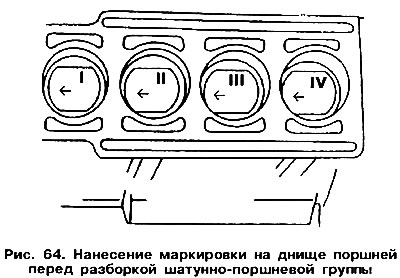
Each connecting rod and piston group must be marked with the number of the cylinder from which it will be dismantled. This is best done with paint, applying cylinder numbers to the piston crown (pic. 64). The numbers must be supplemented with arrows indicating the direction of installation of the piston to the front of the engine.
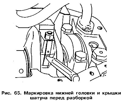
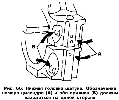
When separating the piston with the connecting rod from the bearing cap, remember its position. Before removing the connecting rod bearing cap, it is recommended that both the cap and the lower head of the connecting rod be marked at the same time by marking the cylinder number on one side (see fig. 65). The cap and bottom head of the connecting rod are provided with lugs during manufacture (pic. 66), which, when assembled, must be directed in the same direction (along the car).
 |  |
You also need to mark the liners of each connecting rod. In order not to confuse the upper and lower liners, also mark them with paint.
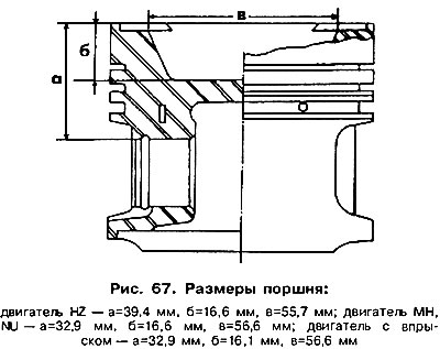
Pistons differ in the depth of the recess in the bottom. If you want to replace the pistons, you need to measure the distance «b» (see fig. 67). This is the so-called combustion chamber height for a given type of engine. Pistons to be replaced must have the same depth of grooves in the bottom. There are differences in several recess parameters, which are not the same for all types of engines. On fig. 67 shows the dimensions of pistons designed for different types of engines. It is recommended to remove the pistons as follows.
Remove the connecting rod bearing caps and liners, and then push the pistons with the connecting rods up. Clean the pistons and cylinders of oil deposits.
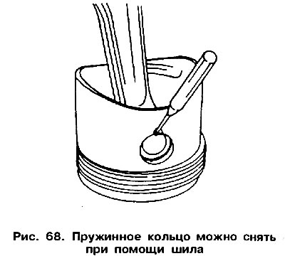
After removing the circlips, knock out the piston pin. Using the groove next to the finger hole, pry with an awl and remove the circlips (pic. 68), The finger is knocked out using a rod of the same diameter as the finger.
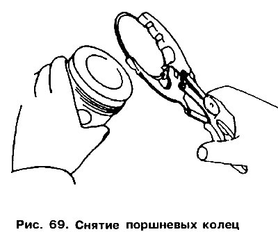
Remove the piston rings from the pistons one by one, using ring pliers (pic. 69), If the ring can be reused, it must be marked. If you do not have piston ring pliers, you can use thin steel plates that are brought evenly around the circumference under the rings. One of the plates must be placed under the lock of the ring so as not to scratch the surface of the piston (see fig. 203).
Details of the connecting rod and piston group after disassembly are shown in fig. 70.
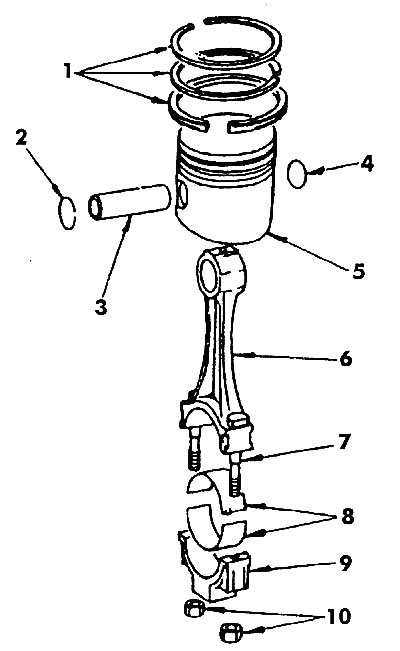
Pic. 70. Connecting rod and piston group: 1 - piston rings, 2, 4 - circlips, 3 - piston pin, 5 - piston, 6 - connecting rod, 7 - bolt, a - insert, 9 - cap, 10 - nut
Visitor comments