
Arrange the connecting rods in the order of cylinder numbering. The lugs on the bottom head and connecting rod cap must face the front of the engine (or according to the marking during disassembly).
Remove covers and inserts, set them aside so as not to mix them up. Remove the bolts.
The arrows on the piston crowns must point towards the front of the engine. Rotate the piston ring locks 120°. 70 shows how the piston ring locks should be located in relation to the axis of the piston pin.
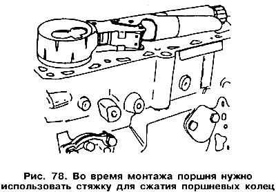
Put on the coupler on the piston rings, as shown in fig. 78, and push the rings into the grooves. Check that the rings are completely in the grooves. Wrap the bottom head of the connecting rod with polyethylene to prevent damage to the surface of the cylinder mirror.
Turn the crankshaft so that the connecting rod journal of the desired cylinder is at BDC. Insert the connecting rod from above into the cylinder. The cylinder block must be laid on its side so that the lower end of the connecting rod can be brought to the generously lubricated crankshaft crankpin by removing the protective material (polyethylene). This method eliminates the possibility of damage to the cylinder mirror or the connecting rod journal of the crankshaft. The connecting rod bushing should already be in the bottom end of the connecting rod with the lug installed in the groove of the bottom end of the connecting rod.
Insert the piston into the cylinder, the rings will also alternately enter the cylinder, and the lower head of the connecting rod will come into contact with the crankshaft journal.
Lubricate the connecting rod bearing cap liberally with engine oil. Place the cap on the connecting rod bolts and lightly tap it. Check again that the lugs on the lower head and connecting rod cap (see fig. 66) were on the same side. This is the last opportunity to correct a possible mistake.
Lubricate the nuts on the cover. Tighten the nuts as follows:
- in the first phase alternately with a torque of 30 Nm,
- in the second phase turn them 90°.
After installing the connecting rods, rotate the crankshaft a few times to check the build quality.
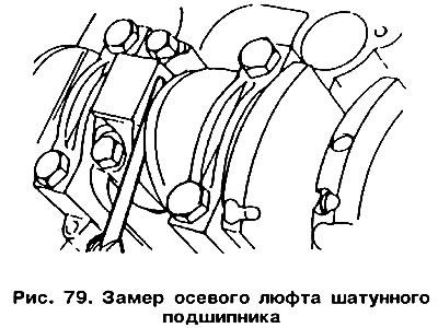
Once again check up marking of all rods and correctness of installation of pistons. Check the gap between the side surface of the connecting rod bearing cap and the crank web with a feeler gauge (pic. 79). This is the axial play of the connecting rod bearing, its value should not exceed 0.40 mm.
Carry out the remaining operations in the reverse order of disassembly, completing the assembly by installing the oil pan.
This operation must be performed before assembling the engine.
The pattern of normal surface wear is shown by the line «A», and the line «1» indicates excessive wear caused by lack of oil.
Visitor comments