
Next, disconnect the engine from the gearbox. When removing the gearbox, do not bend the input shaft.
Remove clutch components and parts (chapter).
While holding the flywheel ring gear with a screwdriver, remove the bolts. This is usually enough to loosen the bolts. Having fixed the engine well, unscrew the bolts.
Remove the cylinder head together with the intake and exhaust manifolds (see chapter). This is also associated with the removal of the timing mechanism drive and toothed belt, described in chapter.
On the inner surface of the toothed belt, mark the direction of its movement with paint. Remove the oil pan (chapter 3.9). Remove the oil pump (chapter 3.9).
If only the crankshaft is removed, the pistons and connecting rods can remain in the cylinder block. Otherwise, dismantle the connecting rod and piston group as described in chapter 3.5. If the pistons with connecting rods remain in the cylinders, mark the connecting rod caps, remove them and leave them with liners. Don't forget to replace the connecting rod bolts.
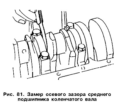
On the front of the cylinder block, attach the indicator so that the indicator rod can be attached to the toe of the crankshaft. Using a screwdriver, move the crankshaft to one side and set the indicator needle to zero, and then move the crankshaft to the other side. The indicator reading is the amount of axial play of the crankshaft. Record the measurement result. If the amount of play exceeds 0.20 mm, this must be taken into account during assembly. In any case, it is recommended to replace the thrust half rings with new ones, either of the same size if the gap is normal, or with thicker bushings to bring the play back to normal. If you do not have an indicator, the end play can be measured with a feeler gauge inserted between the front of the connecting rod bearing cap, the outer surface of the middle bearing and the crank web of the crankshaft (pic. 81).
Remove bolts 7 (see fig. 39) fastening the front cover 20 with an oil seal and remove the cover together with the gasket.
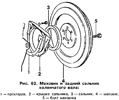
Remove the back cover in the same way (pic. 82).
Loosen the main bearing cap bolts, loosening them evenly «criss-cross», and then remove them one by one. Check that the cap numbers are clearly visible. Cover No. 1 must be on the drive side of the gas distribution mechanism.
Remove the main bearing shells from the crankshaft journals and place them on their respective caps. Remove both thrust half rings from the central bearing, which serve to adjust the axial play. Carefully remove the crankshaft from the cylinder block.
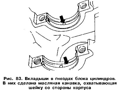
Remove the remaining earbuds from the case and place them in the order in which they were removed. The bushings are provided with grooves for oil supply and must be placed in their original places during installation (pic. 83). Remove the lower thrust half ring from the middle bearing of the crankshaft.
Visitor comments