



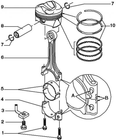
Pic. 2.154. Piston and connecting rod: 1 – a bolt of fastening of a cover of a rod, 30 Н·м + to tighten on 1/4 about. (90°); 2 - pressure reducing valve, 27 Nm; 3 - oil injection nozzle; 4 - connecting rod cover; 5 - bearing shell; 6 - connecting rod; 7 - retaining ring; 8 - piston pin; 9 - piston; 10 - piston rings
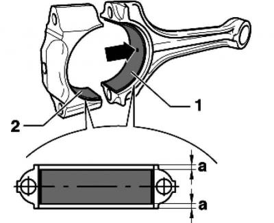
Pic. 2.155. Mounting position of earbuds
Bearing shells
Bearing shell 1 with a hole for the oil lubrication channel of the connecting rod.
Bearing shell 2 without hole for connecting rod cap.
Insert the bearing shells into the connecting rod and the connecting rod cap in the middle.
Dimension A must be the same on the left and right.
Visitor comments