



Contents: Removal ↓ Installation ↓
Removal
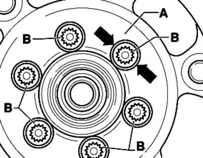
Fig. 2.147. Installation position of flywheel bolts
Turn flywheel A so that bolts B are centered relative to the holes (fig. 2.147).
Note: To avoid damaging the dual mass flywheel during removal, bolts B must not be removed with a pneumatic screwdriver. Bolts B may only be removed by hand.
When unscrewing bolts B, make sure that the bolt head does not jam against the flywheel.
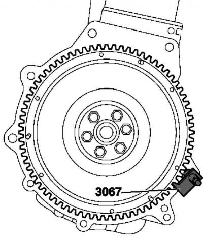
Fig. 2.148. Installing the counter support
Insert the counter support into the hole on the cylinder block (fig. 2.148).
Mark the position of the flywheel relative to the engine.
Unscrew the flywheel.
Installation
Installation is carried out in the reverse order, taking into account the following.
The bolts need to be replaced.
Tightening torque: dual mass flywheel to crankshaft – 60 Nm +90° (1/4 turn)
Visitor comments