



Unscrewing and screwing the driven disk
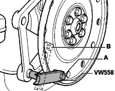
Fig. 2.149. Counter support fixing diagram
Secure the counter support to the driven disk using an M8x45 hex bolt. Install two M10 hex nuts between the counter support and the driven disk (fig. 2.149).
Place of installation of counter support A for unscrewing, B for tightening.
Installing the slave disk
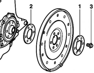
Fig. 2.150. Slave disk components
Install the driven disk using a slotted washer 1 (fig. 2.150).
Insert and tighten new bolts 3 to 30 Nm.
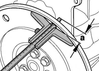
Fig. 2.151. Measuring the protrusion of the driven disk
Measure the value A in three places and calculate the average value (fig. 2.151).
(The information is available on the website www.VWMANUAL.ru)
Nominal size 19.5–21.1 mm.
Note: It is measured through the hole in the driven disk to the milled surface of the cylinder block.
Note: If the nominal value is not reached
Note: Remove the driven disk again using the compensation washer 2 (fig. 2.150). Retighten bolts 3 to 30 Nm.
Tighten the bolts to 60 Nm and turn them 90° further (1/4 turn) (the stretch can be performed in several approaches).
Visitor comments